• Steel Soldiers now has a few new forums, read more about it at: New Munitions Forums!

  • Microsoft MSN, Live, Hotmail, Outlook email users may not be receiving emails. We are working to resolve this issue. Please add support@steelsoldiers.com to your trusted contacts.


Battery imbalance. Related to dual voltage? Trying to understand electrical system

blutow

Well-known member
357
498
63
Location
Austin, TX
I'm trying to understand the design of the electrical system on my m1123 and trouble shooting a battery balance issue. I have the 200a dual voltage generator. Everything seems to be working OK, but I have a pretty significant battery imbalance. It's not the batteries because I've swapped positions with them and the problem just moves to the other battery.

My "rear" battery is always higher than the front and it looks like my charging system is somehow pushing more amps to that battery (at least for a while after starting the truck). So, I'll have the rear battery reading ~15v and the front reading ~13v. After running for a little bit and as the amps drop (as batteries are topped off), the voltage normalizes a bit, but I'll still be at 14.5v on the rear and 13.5v on the front. 13.5v is not high enough to properly charge and condition the battery.

I'm wondering if this is somehow related to the dual voltage system and maybe the 12v feed is feeding the rear battery. I see that there are some wires going to the positive terminal on the rear battery and I'm not clear what is going on there. Pic below are the wires I'm referring to (yellow heat shrink on one of the wires). I also notice that my 12v output on my voltage regulator is putting out a little over 15v when the truck is started and then eventually settles to down to around 14.4v after it's been running a while. I found the TM that goes through the alternator check and repair, but I can't find anything that provides an overview of the electrical system and what is going on or how it should behave.

PIc below shows the positive terminal on the rear battery with the wires hanging off (yellow heat shrink on one of the wires). I assume this is for a 12v feed, but not clear what it's for. I'm also not clear if it's connected to the 12v output of the generator. My 12v generator output is more than half the output of the 24v output, so it would make sense that it's giving the rear battery more volts if that is a connection to the generator. Maybe a problem with my voltage regulator with the 12v side a bit high? Ideally, I need to be charging both batteries at 14v or higher and the front battery is not doing that with the current behavior. Any thoughts? Is there a TM somewhere that explains how the mixed voltage system works and whether this could affect charging?
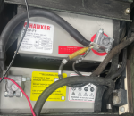
1650642334069.png
 

mechanicjim

Member
88
34
18
Location
Chicago il
The reason for the imbalance is you actually need more load on the 12v side of things. the design of the dual voltage was the military wanted to use 12V items in a 24V vehicle. to do this they tapped power off the lower 12v battery, the "14V" tap on the regulator provides up to 50 amps to the rear battery to help keep it being discharged too much from the 12v loads. similar to a battery equalizer, but just like an "equalizer" if the lower battery is a higher voltage than the upper battery the system can not compensate for this.
 

TOBASH

Father, Surgeon, Cantankerous Grouch
Steel Soldiers Supporter
3,272
3,010
113
Location
Brooklyn, NY
To keep your batteries more balanced, you should switch batteries back and forth meaning that the number one battery should become the number two battery and vice versa every three months.

Edit - you can also add a third motorcycle battery to be charged by the 12V circuit for use with the transmission
 
Last edited:

Mogman

Moderator
Staff member
Moderator
Steel Soldiers Supporter
5,952
8,296
113
Location
Papalote, TX
Check the 14V tap on your regulator, I do not see a connection to the middle of the batteries, but you do not show both connections.
Make sure the 14v tap on the regulator is reading the same as the connection between batteries.
If the voltage is the same it could possibly be a bad regulator
 

Autonomy_Lost

Well-known member
658
1,452
93
Location
Pennsylvania
To keep your batteries more balanced, you should switch batteries back and forth meaning that the number one battery should become the number two battery and vice versa every three months.
Is this true even if you dont have a dual voltage alternator? That sounds like something I don't have time for and will never do lol.
 

Mogman

Moderator
Staff member
Moderator
Steel Soldiers Supporter
5,952
8,296
113
Location
Papalote, TX
Check the 14V tap on your regulator, I do not see a connection to the middle of the batteries, but you do not show both connections.
Make sure the 14v tap on the regulator is reading the same as the connection between batteries.
If the voltage is the same it could possibly be a bad regulator
Sorry, my bad you do show the connections between batteries, man I am getting old and was on the phone with my sister,,,, but still check it out.
The wire with the yellow sleeve goes to your 14V tap on the regulator, the other should feed the transmission
 
Last edited:

blutow

Well-known member
357
498
63
Location
Austin, TX
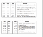
Thanks for the replies. Based on the feedback, it does sound like that yellow insulated wire on the back battery is a power supply from the 12v generator output. After doing more testing, it see that the 12v output runs high for a bit (I've seen it as high as 15.4v), but settles down after a bit. I'm wondering what exactly is controlling the 12v output voltage since it's not constant. The 24v output is much more consistent at around 28.4v.

I'd like to believe the 12v output is smart enough to be dynamically balancing the batteries, but I don't see any reference to that. The good news is that the batteries actually seem to get pretty balanced once I let it run for a bit and the 12v output reduces the voltage. So maybe there is some balancing function there, but I'd like to find something that explains what is going on with the system. The chart below just gives the appropriate test ranges for the alternator, but doesn't really say what controls the output voltage. You can see from the TM charts below that the 12v output should be below 15v, but doesn't say to stop the test unless it hits 15.5v. Mine runs at 15.4v for a while, but eventually settles well under 15v and I've even seen it running under 14v, so I assume something is controlling it or it's got a problem.


1650651702409.png
 

Retiredwarhorses

Well-known member
Steel Soldiers Supporter
4,265
3,885
113
Location
Brentwood, Calif
If your taking a voltage reading from the rear battery while engine is running, of course you have 14.5 volts, the 14v tap feeds the rear battery off the regulator, it’s designed this way to prevent an inbalance due to the draw from the TCM and other 12v accessorie.
 

blutow

Well-known member
357
498
63
Location
Austin, TX
If your taking a voltage reading from the rear battery while engine is running, of course you have 14.5 volts, the 14v tap feeds the rear battery off the regulator, it’s designed this way to prevent an inbalance due to the draw from the TCM and other 12v accessorie.
Thanks. Yeah, I get the concept, just wondering how it works. I figured there are no fancy electronics here comparing voltages between the batteries, but maybe there is some simple logic/method in the voltage regulator keeping a balance? I just assumed it was analog based on the wide acceptable operating range in the manual. Keeping a 24v bank balanced while pulling 12v off one of the batteries seems like a challenging approach, but it might just be that I’ve never run across it before.

In theory, you could use a shunt to measure amp hours in and out on the 12v leg, but again that’s pretty sophisticated stuff and I don’t think the shunt in my hmmwv is wired to measure that way.
 

Sigi

Member
66
82
18
Location
Portland/OR
If you have two batteries in series, the voltage on each battery depends on the internal resistance of the battery. No two batteries are identical. That is why charging two 12V batteries with a 24V alternator will drift out of balance over time. If you draw one battery down with 12V loads, balance gets worse. A dual voltage alternator will help with 12V loads while running. It is still a good idea to check balance once in a while and top off the lower battery.
 

blutow

Well-known member
357
498
63
Location
Austin, TX
blutow, Amp hours is a measure of power that can't be done with a shunt by itself. Shunts only measure current.
Yes, just saying that you can get to amp hours once you have the current from the shunt (and obviously the voltage and duration). I'm not saying the hmmwv is using it's shunt that way. I assume there is nothing "intelligent" going on in this system like with a modern car with shunt and smart alterntor. I don't know that for sure and just threw it out as technically possible. Honestly, I don't understand what the shunt is used for in the hmmwv. I read somewhere that it just provides a way for test equipment to see current, but it seems really dumb to install one on every truck when current is such an easy thing to measure with a clamp on meter. I like to think the shunt is used by something other than test equipment.

I'm still wondering what is driving the voltage change on m 12v output and whether it's normal behavior. I tested it again on a drive tonight while watching the voltage. When cold, it always starts at around 15.4v and slowly fades down to a more reasonable ~14.2v. But that is after 10+ minutes. The TM says to wait for the voltage to settle, but I read that to mean seconds, not 10 minutes (but it doesn't actually specify). I really don't like the idea of pushing over 15v to the battery, but I'm not too worried since it's not doing it for an extended period. My concern is that the output voltage should be more constant like the 24v side and maybe something is wrong with the regulator. I'd hate for it to "get stuck" at over 15v and potentially damage the battery.
 

simp5782

Feo, Fuerte y Formal
Supporting Vendor
12,095
9,260
113
Location
Mason, TN
Always easier to run a 24v brushless alternator and 24 to 12v eaton equalizer.

32months + 200k miles on the batteries, equalizer, alternator.

Never need to "top off" or "switch batteries" like some folks claim. Most people buy cheap batteries, that is the issue.

Buy a battery with a 4yr free replacement and not worry it

The evil wire only gets the batteries when it is a 24v system and you are tapping off of the 12v side.


You should always have your 12v pulling off the + post on the negative battery for any system
 

blutow

Well-known member
357
498
63
Location
Austin, TX
Always easier to run a 24v brushless alternator and 24 to 12v eaton equalizer.
That eaton box makes a lot of sense. Is the stock dual voltage hmmwv regulator doing the same/similar thing to keep things reasonablfy balanced? From voltage behavior I'm seeing, the regulator is clearly doing something different between the 12v and 24v outputs.
 

simp5782

Feo, Fuerte y Formal
Supporting Vendor
12,095
9,260
113
Location
Mason, TN
That eaton box makes a lot of sense. Is the stock dual voltage hmmwv regulator doing the same/similar thing to keep things reasonablfy balanced? From voltage behavior I'm seeing, the regulator is clearly doing something different between the 12v and 24v outputs.
The issue I have with dual voltage alternators is the draw and lighting surge. Have a few trucks with the dual voltage neihoffs. At night you can see the lights dim with the load. Like a blower or wipers.

The dual voltage gauge is showing a draw from both sides when certain things activate even on just 12v. It is just the alternator designed to output when the exciter wire calls for it. Rather than an alternator putting out a steady voltage all the time. Even with remote sense it doesn't let you see the draw thru the gauges or lights with their pulse.

The equalizer doesn't do it with even 85amp draw
 

T9000

Well-known member
Steel Soldiers Supporter
473
360
63
Location
California
Thanks for the replies. Based on the feedback, it does sound like that yellow insulated wire on the back battery is a power supply from the 12v generator output. After doing more testing, it see that the 12v output runs high for a bit (I've seen it as high as 15.4v), but settles down after a bit. I'm wondering what exactly is controlling the 12v output voltage since it's not constant. The 24v output is much more consistent at around 28.4v.

I'd like to believe the 12v output is smart enough to be dynamically balancing the batteries, but I don't see any reference to that. The good news is that the batteries actually seem to get pretty balanced once I let it run for a bit and the 12v output reduces the voltage. So maybe there is some balancing function there, but I'd like to find something that explains what is going on with the system. The chart below just gives the appropriate test ranges for the alternator, but doesn't really say what controls the output voltage. You can see from the TM charts below that the 12v output should be below 15v, but doesn't say to stop the test unless it hits 15.5v. Mine runs at 15.4v for a while, but eventually settles well under 15v and I've even seen it running under 14v, so I assume something is controlling it or it's got a problem.


View attachment 865544
If indeed the overall stack voltage stays consistently at 28.4V regardless of what the 14V mid-point is doing then here is another scenario to consider.
What it appears to be happening from what I read is that while the mid-point rises to 15.4V the other battery goes down to about 13V, which would indicate that there is a very large load on the 13V battery that shifts the midpoint up because the 28.4V source can deliver plenty of current and maintain the overall stack voltage.
The 14V DC regulator may not actually deliver 15.4V, but it may look that way if the mid-point is shifting up due to the higher current draw on the other battery, which affects that leg impedance of the divider.
You could easily test this theory by adding a diode in the 14V line or even a resistor (like 10 ohms 10W) and measure on its both sides. If I understand the data I am reading correctly, you should see the battery side of the diode/ resistor increasing to 15.4V while the 14V DC regulator stays lower, pointing that the mid-point is being pulled by a load across the battery that measures about 13V.
I excluded the possibility that one battery has a disproportionately higher/ lower internal resistance than the other, based on your observation that when switching the battery location, the voltage stayed with the location, it didn't follow the battery.
You could also measure the voltage drop under load across the mid-point cable connecting the two batteries in series, if it has a bad connection or somehow a higher resistance it will affect the voltage at the mid-point based on where you are measuring it, but I doubt that you are not measuring each battery right at its terminals.

Here is a scope shot of how my alternator looks like, it has a ripple of about 2.5V pk-pk - (if you have a scope, take a closer look at what;s going with the 14V line)

1650866483114.png

I built a simple on-board voltmeter that shows each battery voltage to keep an eye on their balance (top meter = front battery):

1650867089115.png

I agree that the system doesn't have any smarts in it, it is built to deliver the main at about 29V and uses the 14.5V DC regulator only on the lower battery (connected to the chassis ground). It is possible that the DC regulator was designed to output 1/2 of the input voltage that it gets from the alternator, which would keep the batteries relatively balanced, not counting the cables voltage drops.
This configuration works well when the expectation is that the lower battery will always have more load than the other battery, but in your case something seems to draw more current from the top/ floating battery in the beginning. I don't know what that could be and maybe others can comment.

Hope this provides another datapoint.
 
Last edited:

T9000

Well-known member
Steel Soldiers Supporter
473
360
63
Location
California
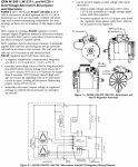
Not sure what model alternator you have and here is the 200A dual-voltage alternator N1225-1 schematic & operation:

1650919081407.png

From the schematic, there are two scenarios that would create the symptoms described:

1. If the 14V regulator would be driving the 15.4V, the whole stack voltage would rise to a total of 15.4V (regulator output) + Vbatt_top (if the Vbatt_top was charged to about 13.5V/ 13.7V when you had it switched in the lower position the total voltage should be around 29V, slightly higher than the regular alternator output of 28.4V) as the regulator can supply up to 50A and the batteries are not totally discharged and there is nothing close to 50A of loading on the 14V line (presumptions) - in this case the issue could be the regulator, which from what I hear is SCR based (not 100% sure), I would put a scope on its output to see if there are any oscillations/ ringing or other instability which the DMM would average it out.

2. If the 14V voltage regulator is not the one driving the voltage up (as I mentioned in the previous post), then the total stack voltage will not rise above the nominal alternator voltage no mater how high the mid-point goes (there are over-voltage protection points at 32V & 16V which disable the outputs if any of the two occurs). If the top/ front battery goes down in voltage while the mid-point raises and the stack voltage stays the same, it would indicate that there is another lower impedance current path (load) around the top/ front battery that in the beginning it is shunting the top battery voltage, not allowing it to rise or be balanced with the bottom one.

The presumptions are that the two batteries internal resistance are relatively close to each other and that all other details you provided are accurate.

EDIT: The 14V regulator output is not regulated to 1/2 of the alternator voltage, but to it's own internal reference.

EDIT 2: misspellings, maybe not all of them, moving too fast :)
 
Last edited:

mgFray

Well-known member
Steel Soldiers Supporter
657
909
93
Location
Southern Minnesota
Just as an FYI. I went out to my M998 w/ 200 AMP generator and the 12V charge circuit going to the middle positive.

Voltage wise, it matches what you saw. The rear batter (vehicle neutral and middle positive) is at 15V, the front battery (middle negative to vehicle 24V positive) is at 13.7 volts while charging about 29V across both batteries, but this quickly drops off -- but the 15V seems to stay.

I think my take away from this who conversation is I should pull and swap batteries occasionally just to make sure they stay balanced.
 

Mogman

Moderator
Staff member
Moderator
Steel Soldiers Supporter
5,952
8,296
113
Location
Papalote, TX
I was curious enough I pulled the pass seat and fired up the Detroit, waited until the glow plugs stopped pulsing and read exactly the same voltage on the batteries, 28.6V across both of them and 14.3V across each battery, I am powering a transmission (6L80) and a lift pump on the 14V tap.
It does not matter which battery the 14V is connected to, there is like a 2 odd cable between them there will not be any difference if it is connected to the negative of the high side battery or the positive of the low side battery, same-same!!
 
Top
AdBlock Detected

We get it, advertisements are annoying!

Sure, ad-blocking software does a great job at blocking ads, but it also blocks useful features of our website like our supporting vendors. Their ads help keep Steel Soldiers going. Please consider disabling your ad blockers for the site. Thanks!

I've Disabled AdBlock
No Thanks