• Steel Soldiers now has a few new forums, read more about it at: New Munitions Forums!

  • Microsoft MSN, Live, Hotmail, Outlook email users may not be receiving emails. We are working to resolve this issue. Please add support@steelsoldiers.com to your trusted contacts.


Break out box diagram/pin-outs?

Guruman

Not so new member
I'm looking to add some creature comforts to my LMTV to make it more suitable for civilian life, mainly cruise control, remote start, and cab/block heaters.

To make this happen I need to tie into the electrical system for battery, switched power, brake signal, speed signal, etc.

I've seen reference to a breakout box under the dash. Mine is an A0, not sure if that matters, but does anyone have the pinouts for that handy?

I noticed that one of the YouTubers tied into it for his cruise, figuring I can do the same, I just need to know which wires are which.
 
Last edited:

Ronmar

Well-known member
3,270
6,615
113
Location
Port angeles wa
Don’t you have the A0 schematics? They are available here in the back of each tech manual, and if you message me your Email I can send you a reduced file size schematic only that pages faster on laptop or tablet. Foldout 15-17 has the meat of what your looking for. If you pull out the power panel on the underside you will find TB1 which is your combined 12 and 24V distribution terminal block, and TB2 which is your main ground terminal block. The pinouts for these are shown on foldout 15.

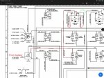
The A0 has no 12v switched ignition, only 24V is switched. But since the truck was wired for many different configurations, there are some candidates in the panel you can re-configure to create a switched 12v Ignition control(Up to the limit of the relay contacts, about 30A). One I have been looking at is K12, the work light relay. It’s socket is mostly already wired and gets 12v from X2 via CB72(Marked in red in this pic) You would have to connect its coil source(pin 86) to the same coil source as relay K2(pin 86 On K12 to pin 86 on K2) so it would come on with the ignition switch… I don’t think there are any open segments on TB1 so you may need to add another TB for 12v ignition distribution… There are all kinds of auto and marine fused distribution panels out there in all shapes and sizes, you would just need to find a place where you can reach it to access it’s fuses… there are also quite a few unused fuses in the existing panel that could be re-purposed to service 12v ign loads…

Any larger loads(heaters) will probably need their own appropriately sized relay and wire directly from X2…
 

Guruman

Not so new member
Don’t you have the A0 schematics? They are available here in the back of each tech manual, and if you message me your Email I can send you a reduced file size schematic only that pages faster on laptop or tablet. Foldout 15-17 has the meat of what your looking for. If you pull out the power panel on the underside you will find TB1 which is your combined 12 and 24V distribution terminal block, and TB2 which is your main ground terminal block. The pinouts for these are shown on foldout 15.

The A0 has no 12v switched ignition, only 24V is switched. But since the truck was wired for many different configurations, there are some candidates in the panel you can re-configure to create a switched 12v Ignition control(Up to the limit of the relay contacts, about 30A). One I have been looking at is K12, the work light relay. It’s socket is mostly already wired and gets 12v from X2 via CB72(Marked in red in this pic) You would have to connect its coil source(pin 86) to the same coil source as relay K2(pin 86 On K12 to pin 86 on K2) so it would come on with the ignition switch… I don’t think there are any open segments on TB1 so you may need to add another TB for 12v ignition distribution… There are all kinds of auto and marine fused distribution panels out there in all shapes and sizes, you would just need to find a place where you can reach it to access it’s fuses… there are also quite a few unused fuses in the existing panel that could be re-purposed to service 12v ign loads…

Any larger loads(heaters) will probably need their own appropriately sized relay and wire directly from X2…
Thanks Ronmar. This is great info.

I downloaded all of the manuals first thing, but I spent an hour this morning digging through them and not finding what I needed (and getting super sidetracked by other tidbits).

I'll PM you my email for those schematic files, thanks.
 
Top
AdBlock Detected

We get it, advertisements are annoying!

Sure, ad-blocking software does a great job at blocking ads, but it also blocks useful features of our website like our supporting vendors. Their ads help keep Steel Soldiers going. Please consider disabling your ad blockers for the site. Thanks!

I've Disabled AdBlock
No Thanks