cjkeeliii
New member
- 165
- 4
- 0
- Location
- Thomasville, GA
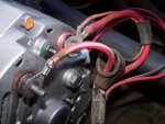
Can someone explain this concept to me and why the passenger side is the isolated ground?
Steel Soldiers now has a few new forums, read more about it at: New Munitions Forums!

Can someone explain this concept to me and why the passenger side is the isolated ground?
We get it, advertisements are annoying!
Sure, ad-blocking software does a great job at blocking ads, but it also blocks useful features of our website like our supporting vendors. Their ads help keep Steel Soldiers going. Please consider disabling your ad blockers for the site. Thanks!