
Keith_J
Well-known member
- 3,657
- 1,328
- 113
- Location
- Schertz TX
Ok, so it equalizes with the engine off. 12.3 volts means about 50% charged 
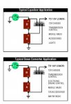
I just found some mention that it divides the input (24 volt) in half to go to the 12 volt side. This would mean the A battery will charge at 1/2 the alternator output, around 14.2. Cool.
I just found some mention that it divides the input (24 volt) in half to go to the 12 volt side. This would mean the A battery will charge at 1/2 the alternator output, around 14.2. Cool.
")