• Steel Soldiers now has a few new forums, read more about it at: New Munitions Forums!

  • Microsoft MSN, Live, Hotmail, Outlook email users may not be receiving emails. We are working to resolve this issue. Please add support@steelsoldiers.com to your trusted contacts.


Compression Testing on MEP 002A/003A

LuckyDog

Member
394
11
18
Location
Freedom, NH
Ok, Where do I find an adapter to test compression on a MEP 002a or 003a??

The glow plug is threaded 7/16x20 (Champion #182 or CH-42)

ALL the "Normal" glow plugs are a metric thread.

Anyone make an adapter or test fitting? My first thought was to just get a 7/16x24 bolt machined to seal the port, then drilled and tapped to accept a small "normal" glow plug test fitting.

I'm not a machinest. I'm an Engineer. (Mechanical) I can do a drawing of the device if someone can make the part....

Ideas????
 
Last edited:

NJ_Toolnut

New member
83
0
0
Location
Bloomsbury, NJ
Hi LuckyDog,

I can make an adaptor if you can post a drawing that illustrates precisely what you have in mind. It might take a couple weeks since I only do machining in my spare time.

Best regards,

Stan
 

LuckyDog

Member
394
11
18
Location
Freedom, NH
Thanks Stan,

I will get a drawing with all the details made up. It might take a couple days for me too. This generator is a hobby endeavor (with long term benifits).

--Paul
 

storeman

Well-known member
1,345
52
48
Location
Mathews County, VA
Guys, I made a tester from a bolt 7/16x24 and drilled through it on my wood drill press (with a very good bit and a couple of tries.

I think I told you about it Stan. When you were here, I was concerned about compression on one MEP-002a and was going to order piece-parts to put together a compression tester and injectors tester.

Next, tapped the head of the bolt to accept standard grease gun metal tube (name unknown), then to a fitting to accept the 2,000 psi gauge I use on a "jerry-rigged" setup I to adjust injectors. Couldn't really get a reading, so I scrapped the unit. I don't know if lack of reading was due to leakage or bad unit. I'm sure there is a better way than I chose.
Jerry [thumbzup]
 

PeterD

New member
622
6
0
Location
Jaffrey, NH
... Couldn't really get a reading, so I scrapped the unit. I don't know if lack of reading was due to leakage or bad unit. I'm sure there is a better way than I chose.
Jerry [thumbzup]
You did include a check valve at the gauge right? Without a check valve you won't get a reading.
 

NJ_Toolnut

New member
83
0
0
Location
Bloomsbury, NJ
You did include a check valve at the gauge right? Without a check valve you won't get a reading.
Hmmm...I think you might see pressure without a check valve if you used a pressure gauge able to react quickly enough to the pressure pulse from the compression stroke, but this pulse might be of such short duration while running the starter motor that even if you had a guage that could react quickly ehough it would be very difficult to read it with any accuracy.
 

LuckyDog

Member
394
11
18
Location
Freedom, NH
Here is a drawing of an adaptor that meets my needs. A mechanic friend has a Snap-On Diesel Compression test set (MT3509). He has an extra fitting with the schrader valve and 1/8 pipe coupler. That is why I show 1/8" NPT on the one end. The "wrench Flats" are just so I can tighten things up and get them back apart. Vise grips would be used otherwise.


I just took the dimensions from a glow plug I have and added the pipe thread to the end. I changed the wrench flats from 1/2" to 3/8" figuring the whole thing can then be made from 7/16" rod.

So, who wants to make these? OR, what else should be added to the drawing? Like I said, this would meet my needs. I think it also has flexibility for others as well.
 

Attachments

NJ_Toolnut

New member
83
0
0
Location
Bloomsbury, NJ
Here is a drawing of an adaptor that meets my needs. A mechanic friend has a Snap-On Diesel Compression test set (MT3509). He has an extra fitting with the schrader valve and 1/8 pipe coupler. That is why I show 1/8" NPT on the one end. The "wrench Flats" are just so I can tighten things up and get them back apart. Vise grips would be used otherwise.


I just took the dimensions from a glow plug I have and added the pipe thread to the end. I changed the wrench flats from 1/2" to 3/8" figuring the whole thing can then be made from 7/16" rod.

So, who wants to make these? OR, what else should be added to the drawing? Like I said, this would meet my needs. I think it also has flexibility for others as well.
LuckyDog,

This is a very professional looking, comprehensive drawing. You have a PM.

Best regards,

Stan
 

LuckyDog

Member
394
11
18
Location
Freedom, NH
Finally tested!!!! NOW What?

So, thanks to Stan (NJ_ToolNut) I was able to attempt a pressure test of the compression on a cold MEP002A.

It has been a long time coming, due to my being a slacker. Stan made a wonderful tool, and quickly too. I just was not gettin' er done.

I bought a Compression Tester from NAPA (PN SER 2428 ) becuase it had a 1/4" NPT end on the hose. It only goes to 300psi on the guage but has a pretty good area after that before it hits the pin again. I'm thinking close to 400 psi before the needle is against the pin.

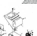
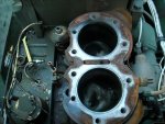
With some simple pipe thread adapters, I was able to get the whole thing together. Cylinder one was real easy. Just take out the glow plug with a 1/2" deep-well socket. Put the adapter in. Cylinder two needed to have the manifold removed to get at the glow plug easily

So it wouldn't try to run, I disconnected the wire plug connector just above the IP. That keeps the fuel selonoid from energizing. Now, just crank it over until the needle stops moving up. Right?

Well! The manual says compression ratio is 19:1. I just figured the pressure would be about 270 psi (a bit less than 19*14.7) WRONG!

Cylinder One was OVER 400 psi in a couple of revolutions. Buried the gauge needle hard against the pin. Cylinder two then only goes up to about 175psi. BUT I probably fubared the gauge when it hit the pin on cylinder one. Back onto cylinder one. Yep, still will go over 300. (Stopped cranking before it hit the pin).

SO, off to do more research. I now have a means to test the compression pressure. What should it REALLY be though?


7-8.1. ENGINE COMPRESSION TEST.
The engine cylinder compression tests of this
paragraph may be used to determine the condition of
engine valves, pistons, piston rings, and cylinders.
Normal cylinder pressure should be between 350 to 450
psi, depending upon engine condition. Corrective
maintenance should be considered if cylinder pressure
is below 325 psi or if there is a pressure difference of
15% or more between cylinders. These pressure ratings
apply to a warm engine at cranking speed (approximately
300 rpm).


The rest of this post is just engineering ranting.


Wikipedia to the rescue. Diesel Engine Compression Ratios states a compression ratio between 18:1 and 23:1 for indirect injection engines. That agrees with the military manual statement of 19:1. A few more lines down, I see an equation for the pressure. It uses "specific heat ratio". :doh: Now my thermodynamics teaching is coming back to me. In simplistic terms, compression in an engine is an adiabatic process. Pressure * Volume^(gamma) = Constant. (gamma is the specific heat ratio of the air ~1.4).

Compression ratio = Volume at BDC divided by Volume at TDC. Some simple math and I got the equation for the pressure in the wikipedia article. Wikipedia also has Compression_ratio_versus_overall_pressure_ratio table.

So now I think the pressure should be around 900 psi. Obviously more than the gauge I have now. But I am still guessing at what the correct pressure is.

--Update-- Since now I know the pressure, it just goes to show that in theory there is no difference between theory and reality. In reality.... 8)
 
Last edited:

Speddmon

Blind squirrel rehabiltator
Super Moderator
Steel Soldiers Supporter
4,640
28
38
Location
Cambridge, Ohio
no idea what it should be, but I would think a good liquid filled 1000 PSI hydraulic gauge would do the trick. Kudos to NJ_Toolnut on the adapter as well.
 

LuckyDog

Member
394
11
18
Location
Freedom, NH
Found the Compression Test pressure!!!

So, after some sleep, I decided to "RTFM" again.

I love PDF files. I searched the -34 manual for cylinder pressure.

"7-8.1. ENGINE COMPRESSION TEST.
The engine cylinder compression tests of this
paragraph may be used to determine the condition of
engine valves, pistons, piston rings, and cylinders.
Normal cylinder pressure should be between 350 to 450
psi, depending upon engine condition. Corrective
maintenance should be considered if cylinder pressure
is below 325 psi or if there is a pressure difference of
15% or more between cylinders. These pressure ratings
apply to a warm engine at cranking speed (approximately
300 rpm)."


That paragraph is followed by the steps of how to do the test.

Best of all - using the glow plug adapter, you DO NOT have to remove the injector to do the test as outlined in the manual. I did have to move the intake manifold to get to cylinder two though. Not completely remove it, just lift it up some. Don't know how it would do on an 003.

Now I can continue troubleshooting.

Table 2-3 Step 14. LOW ENGINE COMPRESSION.
 
Last edited:

NJ_Toolnut

New member
83
0
0
Location
Bloomsbury, NJ
Hi LuckyDog,

Thanks for testing the compression testing adaptor I made for you, and for letting us all know it works OK.

Is there any change that can be made to the adapter design to prevent the need to partly remove the intake manifold when installing it in the #2 cylinder head, or is this situation unavoidable due to the location of the glow plug hole relative to the location of the intake manifold and the overall length of the adaptor?

I was happy to see that you posted the TM-34 references describing normal cylinder pressure. 900 psi sounded a little high to me.

Best regards,

Stan
 

VO1960

New member
4
0
1
Location
Chester/NH
Hello Gents,

Just curious as to whether removal of the cylinder shroud cover by way of removing the 4 bolts that hold it on would assist you in the compression test without requiring removal of the manifold. It sure helps a lot when you're just replacing the glow plugs.


Attachments

LuckyDog

Member
394
11
18
Location
Freedom, NH
Hello Gents,

Just curious as to whether removal of the cylinder shroud cover by way of removing the 4 bolts that hold it on would assist you in the compression test without requiring removal of the manifold. It sure helps a lot when you're just replacing the glow plugs.
Good point. I just "assumed" everyone knew that.

Putting the adapter in without removing the manifold is pretty easy if using a socket and universal joint. It was getting the hose attached to the adapter that caused my problem. I used a brass 1/4"NPT coupler with a 1/4" to 1/8"NPT bushing to connect the adapter to the hose. Made for a bit of length.

I am going to be pressure testing cyl #2 again soon. (Spray a little oil in the cylinder and see if its a rings/cylinder or head/valves problem) I will look a little more close at the fitting. Maybe if I use an 1/8" street-elbow I won't need to disconnect the intake manifold.

Mind you - all my experience is on a MEP-002A. Might not be as much an issue on the 003 or cylinders 3 & 4 could be just like #2 on a 002.
 

LuckyDog

Member
394
11
18
Location
Freedom, NH
The insides of cylinder 2

So, I have been playing around with the generator. Cylinder two has been really low. (175psi) and I can't get more than 10 min of run time before it stalls.

I knew part of the problem was blow by. I grabbed a length of 1/2" heater hose and sent the breather out-put (sort of like a pcv valve) into a bucket. Well it ran for more than 10 min but sounded like crap. It also blew about a cup of oil into the bucket during the 12 minutes it ran.

Spraying oil into cylinder 2 and retesting compression brought it up to 225 psi.

So, I pulled the head. Cylinder 1 was soooo beatiful and shiny with gerogeous hatch marks the camera couldn't focus on it.

BUT # 2 looks like this:

The vertical strips are only visible. Can't feel them. Drug my fingernail across it and there isn't any catches (like scratches would)

IDEAS????????
Rebuild, or Try GL again?
 

Attachments

Isaac-1

Well-known member
1,970
48
48
Location
SW, Louisiana
I would say rebuild, do like the army does, press in a new sleeve, and add a new standard size piston and rings. There was a guy on ebay selling sleeves for a reasonable price a while back (I think around $50 per pair, but that is from memory)

Ike
 

derf

Member
926
13
18
Location
LA
The edge of the piston looks broken.
Further investigation (tear down) is probably warranted.
If you can hone out the strips then a re-ring and a new piston would probably fix it.
How many hours on it?
I'd want to see the main and rod bearings before deciding to rebuild or not.


derf

Member
926
13
18
Location
LA
Also please note compression tests are relative. Unless you have your tester calibrated you have to allow for variances. In this case, looking for 350 and getting 175, you can probably assume the tester is reading OK. But, if you are looking for 350 and getting 325 across the board then you shouldn't assume the tester isn't at least 25 PSI off. If you use your compression tester regularly then you can get a feel for what is accurate. If you just bought one or have a used one then don't assume the number is accurate. On multicylinder applications the differences in the numbers are most telling.

If you don't have a lathe it may be possible to make an adapter from an old glow plug.
 

LuckyDog

Member
394
11
18
Location
Freedom, NH
... press in a new sleeve...
Ike
The MEP-002A and 003A don't have sleeves as far as I can tell. Maybe your thinking of the MEP-004 and above?

The edge of the piston looks broken.
Further investigation (tear down) is probably warranted.
If you can hone out the strips then a re-ring and a new piston would probably fix it.
How many hours on it?
I'd want to see the main and rod bearings before deciding to rebuild or not.
The Hour meter said 7hrs when I got it. Everytime I pull something apart I start to think that might be true. Inside usually looks pristen but outside it looks like it sat for 28 years in the weather.

Maybe that brown glazing is from rust? I have added about 3 hours to it in short intervals just playing with it.

I think I found the reason it was DRMO (DMRO?) Someone else pulled the head before me, I think. I didn't tear any gaskets and none of the bolts complained on the way out. (Ya know, squeaks and tough turning due to rusted threads)

Guess its time to clean my garage and get it off the trailer and inside.
 
Top
AdBlock Detected

We get it, advertisements are annoying!

Sure, ad-blocking software does a great job at blocking ads, but it also blocks useful features of our website like our supporting vendors. Their ads help keep Steel Soldiers going. Please consider disabling your ad blockers for the site. Thanks!

I've Disabled AdBlock
No Thanks