• Steel Soldiers now has a few new forums, read more about it at: New Munitions Forums!

  • Microsoft MSN, Live, Hotmail, Outlook email users may not be receiving emails. We are working to resolve this issue. Please add support@steelsoldiers.com to your trusted contacts.

Connecting Power Cable to RT-524 Radio

rgguin

New member
41
0
0
Location
Alabama
I attempted to connect my power cable to my RT-524 radio for the first time in my M1009. This cable comes from under the dash and is the female end that is the mate to the plug in on the left rear bottom of the RT-524. Cable has #4722/VRC on it. Anyway while I was tryng to connect it sparks came form the plug and I stopped. It appeared one of the female holes was burned a little and the hole was closed up a little where is got hot. All of the radio switches were in the off position before I tried this and the vehicle was running.

Any ideas? :?
 

OPCOM

Moderator
Steel Soldiers Supporter
3,657
27
48
Location
Dallas, Texas
Are you sure the polarity and pinout is right? The power input is the plug in the corner of the mount. On the MT-1029 radio mount, pin B is the +27.5VDC, and pin A is ground. Use caution: "Source voltage polarity reversal is often caused by connecting the power cable leads to the wrong battery terminals. Reversed polarity will damage the mount." Some cables mix up the pinouts with different color wires.. In the mount is a 100A fuse, so if things do not work, you can check this.
 

rgguin

New member
41
0
0
Location
Alabama
This is my experaience at installing a radio. I can see where my 1984 M1009 previously had a radio tray mounted and the source wire from under the dash was in it when I bought it. My Blazer did not have any evidence of the wiring blocks ever being installed, that I have seen in some Blazers on the sidewall under the radio tray. I know the plug in you mentioned at the back of the 1029 mount, but the only way I thought would power it up was to plug in the original wire to the bottom plug under the mount. The prongs match up in size, but maybe I should turn it a certain way to plug it in?? :? Thanks
 

cranetruck

Moderator
Super Moderator
Steel Soldiers Supporter
10,350
75
48
Location
Meadows of Dan, Virginia
All my supply voltages comes via the MX-7777 surpressor/reverse voltage protector and I would higly recommend that if you have electronics onboard, get one. Not more than $30 on ebay (usually).
Shown here in my deuce, but applicable to any MV.
 

Attachments

ONTOS66

Member
433
3
18
Location
Franklin, NJ
In the military rule #1 was to have the ignition off when working on radios. They like things totally idiot proof.
Your power cable should be CX-4720/VRC and connects to J21 main power receptacle (left side), J22 power/audio/control receptacle(center) connects to C-2299/VRC with cable CX-4723/VRC and J23 provides power to MT-1898 if you are using an aux receiver (R-442/VRC)
The idea of installing a supressor, MX-7777, is a good one. That is the box in the lower left hand corner of the previous photo surrounded by the drill, work light, etc.
 

OPCOM

Moderator
Steel Soldiers Supporter
3,657
27
48
Location
Dallas, Texas
well just check the voltages in the pins (holes) of your connector. Use only the pins referenced. some cables have 4 wires and some have a center conductor and shield. If you will use only the VRC radio (and perhaps a supressor like Bjorn has) then make sure nothing else is connected to the unused pins. An ohm-meter can help here as you can verify the connections on the power cable and also se that the mount's power pin is not shorted to ground.
 

ida34

Well-known member
4,118
31
48
Location
Dexter, MI
Go ahead and rub it in Bjorn. The ring mount reenforcement in my cab prohibits any kind of installation like that. I got the fuel cub. I appreciate it. I think I will cut off the corrosion and tack on a washer. I just need to find the right one now. I will also treat it with rust inhibitor. Thanks for the help.
 

rgguin

New member
41
0
0
Location
Alabama
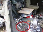
I got it going today. Here is what happened. I thought the plugs were idiot proof :?: This was my first attempt too connect a military radio up. I looked at the plug and saw the prongs were all the same size. If I had examined the power cable plug closer I would have seen an "A", "B", "C", and "D" molded in the plastic next to each prong. I also would have seen the same thing on the tray plug. Now that I turned the plug to mate up "A" to "A" and so forth it plugs in without sparks and presto :!: :lol: :D The radio works or least the lights come on and I have speaker static. Now to get the correct antenna wires :?: My antenna mounts are at the rear of my 1984 CUCV so I need a 10 ft. or so cable. I see some have two cables one smaller than the other?? Do I need the CX-4722/VRC cable for the antenna wire? What do I need for the smaller wire that goes to the antenna mast?

So in this case an idiot can mess up :? Is there any chance of running the battery down leaving the radio turned off, but with the power supply connected?? :?: I went ahead and pulled the radio out of the tray plug just in case.

Thanks for all of the good help. Sorry I took so long about getting back to post.
 

ida34

Well-known member
4,118
31
48
Location
Dexter, MI
As long as the radio is off you will have no problem with the batteries. There is supposed to be a small key to keep you from clocking the cable wrong. I guess yours is broken off.
 

rgguin

New member
41
0
0
Location
Alabama
Chuck, don't know about no key? Everything looked to be correct and OK. The power cable plug has the little flip up tap to trun and tighen the plug up after it is connected, but it does not line anything up as far as right or wrong. Looks like they should have made a slot for the plug to fit only one way? The letters ABCD or not easy to see, of course I was not even loking for them the first time. A few "Sparks" later I was! :shock: :shock:
 

ONTOS66

Member
433
3
18
Location
Franklin, NJ
Chuck,

This is from TM 11-5820-401-20-1, it is available on line in .pdf (although the hard copy is handy to have too). See if this answers your questions regarding the two cables:

2-9. RT ANTENNAS AS-1729 AND AT-912. (CONT)
INSTALLATION OF CABLES PRELIMINARY PROCEDURE: Install RT. See paragraph 2-11.
CAUTION
Before connecting cables to the matching unit, turn Rt POWER switch to OFF. Connector pins
may be damaged due to arcing if this precaution is not observed.
NOTE
Always connect the large cable (CX-4722/VRC) to the matching unit connector or J2 before
connecting the small cable (CG-1773/U).
For MX-6707 (MX-2799):
1. Connect plug (1) of Control Cable CX-4722 (2) to Jack J2 (J551) (3) of matching unit (4).
2. Connect plug (5) of RF Cable CG-1773 (6) to Jack J1 (J552) (7) of matching unit (4).

Good luck with your toys!
 

OPCOM

Moderator
Steel Soldiers Supporter
3,657
27
48
Location
Dallas, Texas
http://www.bunkerofdoom.com/txsg/2004atx/339f.jpg

In this picture, the antenna cable is shown connected to the BNC plug above the speaker. Use a 50 ohm cable with BNC connectors in case you do not have the 'correct' cable. (you can get away with an RG-58 CB radio cable (from a GOOD cb store-not radio shack) that has 95% shielding such as Belden cable and Amphenol or equivalent PL-259 connectors soldered on, not crimped, and putting radio shack SO239-to-BNC adapters on the ends.) On the base of your antenna base is also a BNC plug. On the antenna base is a multi-pin connector. There is a cable that goes from this to the radio. It plugs into the connector with the flat round cap on it, to the lower left of the speaker. You need the correct cable. Mr. Haney may have it in stock reasonably.

This all said, there is also a knob on the bottom of the antenna base. It turns in one direction only. The knob has positions with frequency ranges on them. It can be set, when the automatic system fails, or if you do not have the control cable. The knob goes to a tuning circuit to adjust the antenna electronically when you set a frequency on the radio. As you change frequencies on the radio, a solenoid inside the antenna base rachets the knob to the correct position. There is also a drain/weep hole in the bottom of the antenna base. make sure it is clear, or the base can fill up with water and then it is ruined.

In case you cannot turn the knob or the automatic does not work, you can take the base apart to investigate. Normally you want the base tuned correctly! but if the radio is on LOW power, you cannot damage it in any case, good antenna, bad antenna, no antenna.. Use this setting till you are sure things are in order.
VE MUSS HAFF ODER!!

I cannot show these things to you because I have upgraded to a SINCGARS type base and antenna that is broadband and requires no such tuning scheme.

HOOAH!
 

poof

Dirty Hippie
568
19
18
Location
Wisconsin, Watertown
Well I finaly got it all together.. and the radio powers up...[thumbzup]

Thanks for all this... I was looking for it in the Radio section.. but still worked out..
Ill post a picture in the Radio section or M151 section...
J.P.:beer:
 
Top