• Steel Soldiers now has a few new forums, read more about it at: New Munitions Forums!

  • Microsoft MSN, Live, Hotmail, Outlook email users may not be receiving emails. We are working to resolve this issue. Please add support@steelsoldiers.com to your trusted contacts.

CTIS

Ok, now I am tracking. You can control the 3 solenoid valves and the pcu function with a pair of jumper wires at the controller connector.

Pin H should have 24V with the switch on.
Pin R feeds the control solenoid.
Pin B feeds the air supply solenoid.
Pin C feeds the deflate solenoid.

Disconnect the connector from the controller and With the ign sw on, if you jumper pin H to R or B or C you shoukd hear the solenoids click in the PCU. If the wet tank is over 85 PSI, jumping B should also deliver air from the air supply.

To work the system:
Start the truck, fill the air tanks and shutdown the engine.
Take 2 jumper wires and twist one end of each together to form a V. Install the point of the V into pin H in the ctis controller connector.
Install one jumper leg from H-R and turn on the ign sw. This should close the control solenoid.
With the second leg of the V jumper, jump H to B briefly(1sec) to give a short shot of air to pressurize the system. You should be able to hear the air flow...

If you wait to long to give a shot of air after you close control, the system may start to dump tire air. Every PCU I have played with will slowly pressurize once control is closed. Once it rises over the ~6 PSI wheel valve pressure, it will start dumping the tires... It may have been designed like this to alert an operator to a shorted control solenoid circuit...

If your plumbing is sound this should open the wheel valves and the entire system should set at wheel pressure untill you remove power from pin R by pulling that jumper or turning off the ign sw.

If you have a leak, the pressure in the system will drop and the dump valves will start venting tire air to match the system pressure. Hopefully any leak will not be too bad and you will have some time to find it, or you must give a shot of air to bump system pressure up to stop the tire dump. You only get a few shots of air out of the wet tank.

Once the wet tank drops to 85PSI, it can not deliver anymore air to CTIS and you will have to refill the tank, either by connecting an external air source or briefly starting the engine. It is way easier to find leaks with the engine off.

DO NOT LEAVE SUPPLY SOLENOID JUMPERED/ON as this can fill tires to unsafe levels With engine running.

If you look at my utube channel under username rronmar, you can see me controlling the 3 solenoid valves in the PCU with 3 pushbuttons in my first CTIS video...
I’m going to attempt this next opportunity. Thanks for the thorough info.
 
Lets start with basics.

First - lets assume (I know.... but for the sake of some simple checks) that someone screwed with the wiring to try to hookup to the unit and communicate because A0 trucks don't have coms ports - they are supposed to use a breakout cable that's never around when you need it......

Second - what is your wet tank pressure at compressor unload? If it's not high enough then the CTIS controller will not do anything and eventually fault out with 5 flashing lights and throw a pressure switch code.

Ronmar posits an interesting theory on the multiple maps depending on how you power the unit..... though I would *think* this would show up as options in the Dana Diagnostics software or instructions which it most definitely does not. So I kind of doubt this is a thing - also I've read multiple reports of people simply swapping in controllers from the trucks with higher pressure set points and having them work at the higher pressure which would seem to indicate that the truck wiring is the same on both applications and it's the module programming that's different.
I should’ve asked, what do you mean by “compressor unload?”
 
Ok, now I am tracking. You can control the 3 solenoid valves and the pcu function with a pair of jumper wires at the controller connector.

Pin H should have 24V with the switch on.
Pin R feeds the control solenoid.
Pin B feeds the air supply solenoid.
Pin C feeds the deflate solenoid.

Disconnect the connector from the controller and With the ign sw on, if you jumper pin H to R or B or C you shoukd hear the solenoids click in the PCU. If the wet tank is over 85 PSI, jumping B should also deliver air from the air supply.

To work the system:
Start the truck, fill the air tanks and shutdown the engine.
Take 2 jumper wires and twist one end of each together to form a V. Install the point of the V into pin H in the ctis controller connector.
Install one jumper leg from H-R and turn on the ign sw. This should close the control solenoid.
With the second leg of the V jumper, jump H to B briefly(1sec) to give a short shot of air to pressurize the system. You should be able to hear the air flow...

If you wait to long to give a shot of air after you close control, the system may start to dump tire air. Every PCU I have played with will slowly pressurize once control is closed. Once it rises over the ~6 PSI wheel valve pressure, it will start dumping the tires... It may have been designed like this to alert an operator to a shorted control solenoid circuit...

If your plumbing is sound this should open the wheel valves and the entire system should set at wheel pressure untill you remove power from pin R by pulling that jumper or turning off the ign sw.

If you have a leak, the pressure in the system will drop and the dump valves will start venting tire air to match the system pressure. Hopefully any leak will not be too bad and you will have some time to find it, or you must give a shot of air to bump system pressure up to stop the tire dump. You only get a few shots of air out of the wet tank.

Once the wet tank drops to 85PSI, it can not deliver anymore air to CTIS and you will have to refill the tank, either by connecting an external air source or briefly starting the engine. It is way easier to find leaks with the engine off.

DO NOT LEAVE SUPPLY SOLENOID JUMPERED/ON as this can fill tires to unsafe levels With engine running.

If you look at my utube channel under username rronmar, you can see me controlling the 3 solenoid valves in the PCU with 3 pushbuttons in my first CTIS video...
I hate to ask this, but if you have a tire that’s 10 PSI lower than the rest and I work the system as you describe above, is it correct to assume the air will take the path of least resistance (to the low tire) and the system will equalize eventually?
 
@Freedom Land Clearing

Here are the pins in the controller to remote control/test the PCU and look for leaks Using a pair of jumpers.

View attachment 904429
Well, using your awesome guidance above, I was able to successfully jump the 24 V power and control. While also testing the inflate and deflate function separately. I seem to have a problem right now because the dump valves are stuck open with the ignition turned off.

Do you suspect I have a stuck solenoid? All six tires are sitting on the wheels. Dang. :)
 
Last edited:
Well,Do you suspect I have a Stocks Illinois? using your awesome guidance above, I was able to successfully jump the 12 V power and control. While also testing the inflate and deflate function separately. I seem to have a problem right now because the dump valves are stuck open with the ignition turned off.

Do you suspect I have a stuck solenoid? All six tires are sitting on the wheels. Dang. :)
I need to add info to this. No sir leaks when the jumpers are in H and R as long as the ignition switch is on. As soon as the switch is shut off, air leaks. The leak locations are the dump valves on both intermediate and rear axles and a location near the front headlight.
 
I need to add info to this. No sir leaks when the jumpers are in H and R as long as the ignition switch is on. As soon as the switch is shut off, air leaks. The leak locations are the dump valves on both intermediate and rear axles and a location near the front headlight.
UPDATE:

when I use the jumper technique to inflate air, air leaks out of the rear dump valves, and a vent location behind the passenger headlight.

I’ve found that I can completely stop the leaking air if I remove the compression nut and line from the PCU vent location. Simply loosening that nut gradually shuts the valves, and all the leaking stops. Here are some pictures. The first one is of the vent port on the PCU that I’m able to loosen to stop the leak. The second picture is the other end of that vent line as it’s going through the floor. The last picture is the opposite end of that where it vents to the atmosphere underneath the cab.

I suspect maybe the PCU has some torn or cracked O rings or diaphragms?

I know, I haven’t said it, but I’m grateful for all the help and attention.

trying to understand, generally, what I have going on with the system overall… Maybe you all are right with the wet tank pressure. I looked at it and all of the fittings and realize there’s nothing there for me to do a quick air pressure check watt or how do you recommend I go about checking my wet tank pressure? maybe, just maybe, that is low, and everything else would be fine as a result?

John

4C1F6FB1-111F-49BA-98AC-5B484C2C058F.jpegFC02FAF6-A773-4435-B27C-1ACEA3811567.jpegC0A096B7-C272-49AE-A34B-09C71ED4101A.jpeg
 

GeneralDisorder

Well-known member
Steel Soldiers Supporter
1,514
4,208
113
Location
Portland, OR
I haven't run across a PCU that didn't need rebuilding yet. You can get new spool valves and o-rings from a couple different vendors. First time I powered mine up it started venting under the dash and wouldn't stop. And my truck is a 2008.
 

Ronmar

Well-known member
3,322
6,698
113
Location
Port angeles wa
Ok, i just helped someone with this same issue, the system deflated all the tires, out in the middle of nowhere… it was a clogged vent…

like I described in the deflate cycle, control seals the PCU, then supply pressurizes it, then deflate connects the PCU to a 6.5PSI relief that drops the PCU pressure to 6.5, and the dumps copy this by dumping tire air trying to get to that same pressure.

OK, you have closed control, given a shot of supply to pressurize and open the wheel valves. Now when you turn off the ign power or pull the control jumper, the control valve should open and vent the PCU to 0, the dump valves should pass that 0 PSI along to the wheel valves that should close(causes a brief dump valve vent).

The control dumps the air from the PCU into that lower plastic cover on the bottom(Covers the solenoid coils). That cover has a fitting that is connected to a port in the floor. Now imagine what would happen if that vent out thru the floor became partly or mostly clogged and the pressure could not drop cleanly to zero. You know like when you select deflate and that 6.5 PSI relief keeps the manifold around 6-7 PSI?

The dump valves don't care what your intent was, they pass the pressure along to the wheels and if it is still enough to keep the wheel valves open, the tires will flow air back to the dump valve vents.…

check that the control vent floor passage is completely clear. Have had a few issues I assisted with where insects have closed that port with mud… it is either that or the control valve is not opening cleanly/fully.

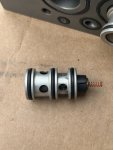
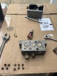
If it is not a clogged floor vent The valve comes apart fairly easily with Oring seals. de-install the valve and remove the bottom cover, then remove the 6 Allen head screws that hold the the two halvs of the valve block together. Here is a pic of a friends valve I opened up(he had a dryer fail internally) got quite a bit of crap out of the valve and the pressure sensor was clogged with crap. There is a little spring on the bottom end of each core, make sure you don’t loose track of it, and a little dab of grease will hold it in place when you re-install the core. i believe Superman has rebuild cores and seals if you need them.

you can start the truck, close the control solenoid and pulse the supply solenoid to add air back to the tires. Low tires will drop the wet tank to the protection cutoff of 85 PSI in about 3 seconds, so 3 seconds on and 15-20 seconds off(till dryer purges). Use a tire gauge to periodically check the fill progress, don’t over-fill the tires, remember the air filled bomb part? This goes faster if you bump up the idle a bit, but it still takes quite a while

remember disconnecting port “C” from the manual page you posted earlier. If you disconnect it, that will vent the system down to the dump valves to 0 and cause the tire valves to close. This will get you back on full tires until you figure out whats up with the control not venting cleanly to atmosphere…


IMG_3208.jpeg
 

Lostchain

Well-known member
Steel Soldiers Supporter
241
509
93
Location
Portland, OR
UPDATE:

I’ve found that I can completely stop the leaking air if I remove the compression nut and line from the PCU vent location. Simply loosening that nut gradually shuts the valves, and all the leaking stops.

That might indicate that the vent line itself is plugged, like from mud wasps or something.. Leave that vent line disconnected at the PCU and see if it behaves normally. If so, clogged vent line is likely your issue, newer units just vent right under the kick-panel, probably due to this issue...
 

Ronmar

Well-known member
3,322
6,698
113
Location
Port angeles wa
If loosening that line from the PCU cover/case to the floors stopped the tire deflate, then that vent line to the floor is clogged… that vent must be unobstructed to atmosphere.

The gentleman I helped a few days ago has an Acella, with a deep water fording package. they connected the lower side of that floor vent to a hose that runs up to their elevated common vent manifold. That added hose was plugged on his. He actually had air coming out around the seal where the plastic lower cover was attached.

on some newer trucks, they did the air systems a little different and added a pressure reg for the fan and rear axle control air on the 6X6 trucks. They ran out of floor ports so like Lostchain said, they just put a vented cover on that port on the PCU plastic cover and it vents into the under dash area… My friend who had the dirty valve shown above(A1R 6X6) vented into the dash.

that nasty valve actually still worked, it was the fouled pressure transducer that was causing his issues, Of course we cleaned it all up anyway and he got new valve cores from Superman…
 
Last edited:

Lostchain

Well-known member
Steel Soldiers Supporter
241
509
93
Location
Portland, OR
I hate to ask this, but if you have a tire that’s 10 PSI lower than the rest and I work the system as you describe above, is it correct to assume the air will take the path of least resistance (to the low tire) and the system will equalize eventually?
So the quick answer to this is yes, the system will eventually equalize. What will happen though is that during the check cycle, the CTIS controller will see pressure dropping as the higher PSI tires inflate the lower PSI tire and the system will throw a 4 light blink code to indicate the tire imbalance. This is to alert the operator that there is probably a tire going flat. Having stable pressure when checking is a very important part of the CTIS programming and so while troubleshooting the system the first thing you should do is manually inflate the tires to the same PSI to avoid chasing your tail.
 

Ronmar

Well-known member
3,322
6,698
113
Location
Port angeles wa
The dump valves, when dumping tire air out the vent also feed back a little air toward the PCU. If you close control and pressurized the system, then started a deflate by jumping to the deflate pin and then disconnected that, the dump valves will continue to vent, but the pressure in the now resealed PCU would steadily build and halt the dump in 20-30 seconds. You can hear the dump valves slowing their dump as the PCU side pressure builds back up Untill it eventually equalizes and stops the dump completely. You can see this briefly starting minute 3: in the below linked video. I initiated a dump, then released the button/deflate solenoid and you can see the lower number on the gauge(PCU pressure) rising steadily until I give the PCU a shot of supply to halt the dump immediately.

if your vent line is restricted and cannot vent this air being fed back from the dump valves completely to zero immediately, it will work just like the deflate mode, and this returning air can keep the PCU pressure somewhere above the tire valve opening point and the dump valves will match that pressure to the wheel valves and dump all the tire air, 0 f’s given…:)


Lets start with basics.

First - lets assume (I know.... but for the sake of some simple checks) that someone screwed with the wiring to try to hookup to the unit and communicate because A0 trucks don't have coms ports - they are supposed to use a breakout cable that's never around when you need it......

Second - what is your wet tank pressure at compressor unload? If it's not high enough then the CTIS controller will not do anything and eventually fault out with 5 flashing lights and throw a pressure switch code.

Ronmar posits an interesting theory on the multiple maps depending on how you power the unit..... though I would *think* this would show up as options in the Dana Diagnostics software or instructions which it most definitely does not. So I kind of doubt this is a thing - also I've read multiple reports of people simply swapping in controllers from the trucks with higher pressure set points and having them work at the higher pressure which would seem to indicate that the truck wiring is the same on both applications and it's the module programming that's different.
@GeneralDisorder and @Ronmar. My wet tank pressure right at the drain is 111 PSI. Let me know if that is a good location to check. See picture on my setup.

Looking at the TM, if appears I need to tweak the governor to ~120 PSI…is that correct?

Thanks.

John
BE98C2D3-BDFD-4A75-936B-D90D6D07FD82.jpeg
 
@Ronmar and @GeneralDisorder, my air governor is now outputting 130 PSI. I can tweak it a bit to get it to 125 if necessary.

The PCU is out, disassembled and found, overall, it wasn’t too nasty inside but the valves were not easy to get out. Shots of air and lubricant freed them. I cleaned it up, lubed the o-rings and reinstalled. Unfortunately, my 5 flashing lights still exist. Also, that vent tube was plugged as you both suspected.

What’s the chance I have a bad solenoid? Is there a way to test it at the connector?

Also, I remember testing the switch at the wet tank a couple weeks ago and I think it was good, but I’m going to look at it again tomorrow to be sure.

The picture of one of the three valves shows I ripped the seat trying to getit off. Do you know where to source a rebuild kit for it? I literally looked for an hour and yielded nothing.

I’d gladly take ideas on the way forward.

Thanks again.

John
 

Attachments

Last edited:

Ronmar

Well-known member
3,322
6,698
113
Location
Port angeles wa
@Ronmar and @GeneralDisorder, my air governor is now outputting 130 PSI. I can tweak it a bit to get it to 125 if necessary.

The PCU is out, disassembled and found, overall, it wasn’t too nasty inside but the valves were not easy to get out. Shots of air and lubricant freed them. I cleaned it up, lubed the o-rings and reinstalled. Unfortunately, my 5 flashing lights still exist. Also, that vent tube was plugged as you both suspected.

What’s the chance I have a bad solenoid? Is there a way to test it at the connector?

Also, I remember testing the switch at the wet tank a couple weeks ago and I think it was good, but I’m going to look at it again tomorrow to be sure.

The picture of one of the three valves shows I ripped the seat trying to getit off. Do you know where to source a rebuild kit for it? I literally looked for an hour and yielded nothing.

I’d gladly take ideas on the way forward.

Thanks again.

John
You were able to work the solenoids using the jumpers right, so they are probably OK. The best test for the wet tank switch is at the CTIS controller connector. When the tank goes over 117 PSI you snould see it close and complete a low resistance circuit between pin T in the connector and ground.

I would work that governor set point down towards 125 PSI.

it could be that you have a bad pressure sensor on the PCU. While you have the PCU apart, unscrew the sensor and inspect it for any debris in its sensor port. You could also check resistance between the pins in the CTIS controler connector and the pressure sensor connector at the PCU install location. Pins j, b and c (lower case) should connect to pins A, B and C respectively in the pressure sensor transducer connector at the PCU.

You could also probe the wires thru the insulation with a pin to the pressure sensor with controller and sensor connected and powered. it is a 0-5v 0-100 PSI sensor. The controller sends 5v and ground to two of the pins on the sensor and the sensor returns a 0-5v signal based on the pressure it senses. 5v divided by 100 = .05v per pound of pressure, so 14PSI of atmospheric air pressure should yield ~.73V on the sense wire…

contact Superman here on steel soldiers, he had PCU rebuild parts. Great guy to work with!
 

GeneralDisorder

Well-known member
Steel Soldiers Supporter
1,514
4,208
113
Location
Portland, OR
Hate to say it but instead of guessing you *could* build the interface cable, download the free software from Dana and know what the problem is *for sure*.

Do the A0 trucks have ABS? I have the Wabco software too - identified a dirty wheel speed sensor on a truck with it yesterday. Huge time savings when it can tell you which wheel isn't reporting wheel speed instantly!
 

Ronmar

Well-known member
3,322
6,698
113
Location
Port angeles wa
Hate to say it but instead of guessing you *could* build the interface cable, download the free software from Dana and know what the problem is *for sure*.

Do the A0 trucks have ABS? I have the Wabco software too - identified a dirty wheel speed sensor on a truck with it yesterday. Huge time savings when it can tell you which wheel isn't reporting wheel speed instantly!
No ABS on the A0…
 
Top