

READ the first few pages of the Troubleshooting Section of the TM 9-2320-289-34 Tech Manual. It explains how to read the wiring diagrams.
GEN1
Sometimes the TM wiring diagrams don't post all the circuits. The GEN1 exciter circuit is one of those.
The GEN1 exciter circuit is controlled by the heater fuse. Why GM built it this way is anyone's guess. Check it first before any other troubleshooting.
Follow along as I trace the GEN1 circuit in a stock system:
1. From the Negative terminal of the rear battery (same as the positive terminal of the front battery) to the 12v Engine Wiring Harness Block (12v Bus) on the firewall - wire RED 2A - Diagram E-1
View attachment 448078
2. From the 12v Bus to the firewall wiring block - wire RED 2E - Diagram E-3
View attachment 448079View attachment 448080
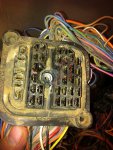
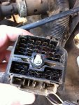
3. Thru the firewall plug to the inside half of the plug and continued to the next diagram - wire RED 2A - Diagram E-3
View attachment 448081View attachment 448079
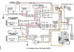
4. From Diagram 3 thru the wiring harness to the ignition switch - wire RED 2C. Thru the switch and to the heater fuse - wire ORN 300 - Diagram E-4
View attachment 448082
-------------------------------------------------------
Now this is where the diagrams are not marked. I have physically traced the wires and have verified the circuit.
The Heater fuse supplies power to both the heater circuit and PIN#5 of the instrument cluster. PIN #5 supplies power to the GEN1 bulb, the 4x4 Indicator Lamp and the Oil Pressure circuit.
I have added the wire to the Diagram
5. From the Heater fuse to PIN #5 of the cluster plug, thru the circuit board and GEN1 bulb back to PIN #8. From PIN #8 of the cluster plug to the interior firewall plug - wire BRN 25 - Diagram E-9
View attachment 448083View attachment 448084
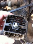
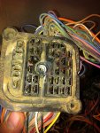
6. Thru the firewall and to the GEN1 excitor plug - wire BRN 25 - Diagram E-9
View attachment 448090View attachment 448091
The brown wire at the GEN1 exciter circuit plug has to read 12v when ever the key is on. The red wire will read 12v at all times
So to sum up. The Heater fuse controls many things: the heater, the GEN1 excitor circuit, oil preasure circuit and the 4x4 lamp circuit. An issue with any of these will cause a low voltage condition and possibly interfer with the GEN1 operation.
Did you also notice the black "goo" in the firewall plug? GM used some type of grease that transforms into this black goo and DOES cause issues with circuits. Taking the plug apart and cleaning the contacts does wonders.
GEN1
Sometimes the TM wiring diagrams don't post all the circuits. The GEN1 exciter circuit is one of those.
The GEN1 exciter circuit is controlled by the heater fuse. Why GM built it this way is anyone's guess. Check it first before any other troubleshooting.
Follow along as I trace the GEN1 circuit in a stock system:
1. From the Negative terminal of the rear battery (same as the positive terminal of the front battery) to the 12v Engine Wiring Harness Block (12v Bus) on the firewall - wire RED 2A - Diagram E-1
View attachment 448078
2. From the 12v Bus to the firewall wiring block - wire RED 2E - Diagram E-3
View attachment 448079View attachment 448080
3. Thru the firewall plug to the inside half of the plug and continued to the next diagram - wire RED 2A - Diagram E-3
View attachment 448081View attachment 448079
4. From Diagram 3 thru the wiring harness to the ignition switch - wire RED 2C. Thru the switch and to the heater fuse - wire ORN 300 - Diagram E-4
View attachment 448082
-------------------------------------------------------
Now this is where the diagrams are not marked. I have physically traced the wires and have verified the circuit.
The Heater fuse supplies power to both the heater circuit and PIN#5 of the instrument cluster. PIN #5 supplies power to the GEN1 bulb, the 4x4 Indicator Lamp and the Oil Pressure circuit.
I have added the wire to the Diagram
5. From the Heater fuse to PIN #5 of the cluster plug, thru the circuit board and GEN1 bulb back to PIN #8. From PIN #8 of the cluster plug to the interior firewall plug - wire BRN 25 - Diagram E-9
View attachment 448083View attachment 448084
6. Thru the firewall and to the GEN1 excitor plug - wire BRN 25 - Diagram E-9
View attachment 448090View attachment 448091
The brown wire at the GEN1 exciter circuit plug has to read 12v when ever the key is on. The red wire will read 12v at all times
So to sum up. The Heater fuse controls many things: the heater, the GEN1 excitor circuit, oil preasure circuit and the 4x4 lamp circuit. An issue with any of these will cause a low voltage condition and possibly interfer with the GEN1 operation.
Did you also notice the black "goo" in the firewall plug? GM used some type of grease that transforms into this black goo and DOES cause issues with circuits. Taking the plug apart and cleaning the contacts does wonders.
Attachments
-
 40 KB Views: 343
 -
 34.6 KB Views: 340
 -
 68.4 KB Views: 336
 -
 83.7 KB Views: 336
 -
 53.8 KB Views: 340
 -
 42.8 KB Views: 347
 -
 83.8 KB Views: 277
 -
 68.4 KB Views: 269
 -
 68.1 KB Views: 334
Last edited:


