The headlight circuit causes many problems for most CUCV users.
The GM design could use some improvements as the Headlight Fuse actually provides power for multiple circuits. We will cover those shortly.
Let's look at the headlights them self first.
Whenever troubleshooting any electrical issue, make sure that your batteries are fully charged and load tested. This is clearly stated on the first page of the Troubleshooting section of the Technical Manuals.
Also take time to read the first few pages of the Troubleshooting section of TM 9-2320-289-20 or the TM 9-2320-289-34 manual. It explains how to read the diagrams and what all the symbols mean and how the wires are labeled for tracing the circuits.
I have taken the wiring diagrams from the Appendix for the above manuals and saved then as a jpeg file. When I am working on a problem I open the picture and color the wire for the circuit I am working on.
Let's get started.
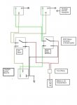
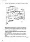
Here is the circuit path for the headlight circuit.
Pic1 - 12v is supplied from negative terminal of the rear battery via wire (8 RED-2A) to the ENG WRG HARNESS BLOCK. This is the diamond shaped 12v Terminal Block on the firewall near the Brake Master Cylinder. The circuit is protected by the Blue fusible link (3 BLU-2B).
Pic2 - The circuit travels thru the Red fusible link (1 RED-2F) and wire (3 RED-2J) to the Firewall Wiring Harness Connector. It travels thru the firewall and out the other side via wire (3 RED-2G)
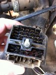
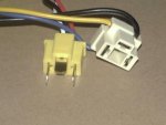
Pic2a - By reading the instructions at the first of the Troubleshooting section it shows where to find the wires on the connector. This is the engine compartment side of the firewall connector
Pic2b - This is the under dash side of the firewall connector
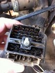
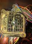
Pic3 - Wire (3 RED 2G) travels to the fuse box to the 30amp Headlight Fuse. It enters the left side of the fuse holder.
***IMPORTANT NOTE ***
If you took the fuse box apart you would not find a wire on the other side of the fuse. Instead you will find a metal jumper that feed the Stoplight Fuse. This is not shown in any of the diagrams and confuses many people.
Pic4 - From the right side of the Stoplight fuse, but still protected by the headlight fuse ( are you confused yet???), the circuit travels thru the Orange wire (3 ORG-914) to the Military Headlight Service Switch on the left side of the dash. The Service switch was added to insure that the "enemy" couldn't see you if you accidently turned on the lights in the battlefield. Without the Service switch turned on many items in the electrical system are disabled. This is all covered in the TM 9-2320-289-10 Operations Manual.
Pic5 - When the Service Switch is engaged the circuit travels the Orange and Black wire (3 ORN/BLK 912A)
Pic6 - Continuing on to the Headlight switch. It attaches to Pin #1 of the switch. The headlight switch supplies power to headlights, tail lights, dash lights and the "dome" light under the dash.
*** IMPORTANT NOTE ***
You will also notice that there is a second orange and black wire connected to Pin #1. We will discuss this shortly
Continued.
For a bigger picture, Right Click on the thumbnail and chose "Open Link in New Window"
The GM design could use some improvements as the Headlight Fuse actually provides power for multiple circuits. We will cover those shortly.
Let's look at the headlights them self first.
Whenever troubleshooting any electrical issue, make sure that your batteries are fully charged and load tested. This is clearly stated on the first page of the Troubleshooting section of the Technical Manuals.
Also take time to read the first few pages of the Troubleshooting section of TM 9-2320-289-20 or the TM 9-2320-289-34 manual. It explains how to read the diagrams and what all the symbols mean and how the wires are labeled for tracing the circuits.
I have taken the wiring diagrams from the Appendix for the above manuals and saved then as a jpeg file. When I am working on a problem I open the picture and color the wire for the circuit I am working on.
Let's get started.
Here is the circuit path for the headlight circuit.
Pic1 - 12v is supplied from negative terminal of the rear battery via wire (8 RED-2A) to the ENG WRG HARNESS BLOCK. This is the diamond shaped 12v Terminal Block on the firewall near the Brake Master Cylinder. The circuit is protected by the Blue fusible link (3 BLU-2B).
Pic2 - The circuit travels thru the Red fusible link (1 RED-2F) and wire (3 RED-2J) to the Firewall Wiring Harness Connector. It travels thru the firewall and out the other side via wire (3 RED-2G)
Pic2a - By reading the instructions at the first of the Troubleshooting section it shows where to find the wires on the connector. This is the engine compartment side of the firewall connector
Pic2b - This is the under dash side of the firewall connector
Pic3 - Wire (3 RED 2G) travels to the fuse box to the 30amp Headlight Fuse. It enters the left side of the fuse holder.
***IMPORTANT NOTE ***
If you took the fuse box apart you would not find a wire on the other side of the fuse. Instead you will find a metal jumper that feed the Stoplight Fuse. This is not shown in any of the diagrams and confuses many people.
Pic4 - From the right side of the Stoplight fuse, but still protected by the headlight fuse ( are you confused yet???), the circuit travels thru the Orange wire (3 ORG-914) to the Military Headlight Service Switch on the left side of the dash. The Service switch was added to insure that the "enemy" couldn't see you if you accidently turned on the lights in the battlefield. Without the Service switch turned on many items in the electrical system are disabled. This is all covered in the TM 9-2320-289-10 Operations Manual.
Pic5 - When the Service Switch is engaged the circuit travels the Orange and Black wire (3 ORN/BLK 912A)
Pic6 - Continuing on to the Headlight switch. It attaches to Pin #1 of the switch. The headlight switch supplies power to headlights, tail lights, dash lights and the "dome" light under the dash.
*** IMPORTANT NOTE ***
You will also notice that there is a second orange and black wire connected to Pin #1. We will discuss this shortly
Continued.
For a bigger picture, Right Click on the thumbnail and chose "Open Link in New Window"
Attachments
-
 34.5 KB Views: 1,131
 -
 82.7 KB Views: 1,149
 -
 100.2 KB Views: 1,095
 -
 55.9 KB Views: 1,136
 -
 52.2 KB Views: 991
 -
 52.2 KB Views: 933
 -
 42.6 KB Views: 928
 -
 35.7 KB Views: 1,206
 -
 68.4 KB Views: 796
 -
 47.6 KB Views: 736
Last edited: