• Steel Soldiers now has a few new forums, read more about it at: New Munitions Forums!

  • Microsoft MSN, Live, Hotmail, Outlook email users may not be receiving emails. We are working to resolve this issue. Please add support@steelsoldiers.com to your trusted contacts.


CUCV-Instrument Cluster Decoded

Warthog

Moderator
Super Moderator
Steel Soldiers Supporter
13,775
227
63
Location
OKC, OK
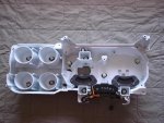
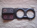
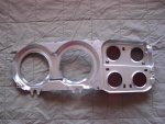
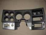
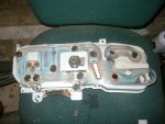
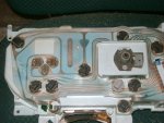
I was troubleshooting my instrument cluster and the TM are good but sometimes hard to understand.

http://www.steelsoldiers.com/electrical/43351-cucv-instrument-cluster-repair.html

I compiled the following and thought I would share.

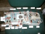
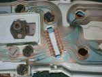
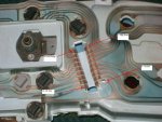
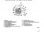
According to the parts manual all bulbs are 168s, except for the GEN2 and between the speedo and fuel gauge. Those two are 194s.

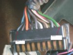
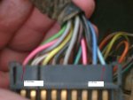
Make sure you read the DIAGRAM.TXT file at the bottom. It is a listing of all the wires, colors and pin numbers for both the diagrams and the cluster/wiring harness.

View attachment Diagram.txt

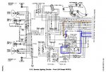
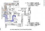
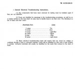
The wiring diagrams are located in Appendix F of the -20 Tech Manual.

***EDIT*** I added another picture, one with the fuse colors.

Without "opening" the pictures - If you right click on the picture and open it in a "Open Link in New Window" they are more readable.
 

Attachments

Last edited:

NMC_EXP

New member
286
12
0
Location
Raton, New Mexico
I appreciate the excellent info, particularly the "open in a new window" suggestion.

Bought a M1009 in October. It has several instrument panel problems. The work I've done so far leads me to believe dirty contacts may be the root cause at least some. e.g. idiot light not working - remove the bulb - check bulb continuity - is OK - plug bulb back in - bulb now works.

Voltmeter was dead - removed the gage - checked resistor - was OK - reinstalled voltmeter - started engine & voltmeter worked - shut it down but on next start the voltmeter was dead again.

Think I'll grind down an old ignition point file narrow enough to fit the female side of the pigtail connector female side and file them a bit. They're all kinda grungy.

Regards

Jim
 

Scarecrow1

New member
1,355
1
0
Location
Florence , S.C.
The pencil is a great tip ,also I like to use a product by permatex called Dielectric Grease... this will provide a better contact and keep the contacts from messing up again,,,,,:razz:
 

panama

Member
123
21
18
Location
Miami, FL
Warthog that text file is invaluable (and time saving). It just so happens that I have my dash on the kitchen table too! I was thinking about moving my GEN1 and GEN2 lights and was about to figure out the color scheme of the wires...thanks for saving me the time.

If you need those "button" sockets for the lights they are NAPA part # LS6501. I replaced one missing and one chewed up socket. I'm sure you already new the bulbs are 168 style (194's will work too).

Some rubbing compound buffed out most of the scratches out of the lens cover.

I also painted the front of the green instrument / printed circuit mounting panel gloss white to help reflect more light:

Krylon: Products: Fusion for Plastic®

While it was out I also scrubbed 25 years of grime off the outer bezel and painted it with Dupli-Color TP70 Trim Paint. It turned out awesome...not too shiny...not too flat...more of a satin:

Trim Paint

I replaced my ratty old voltmeter with a nice VDO. Just remember the 330 ohm resistor, in line with the positive, to knock down the voltage.

Among missing and incorrect fuses and blowing off dust and dirt it has turned into a real project. Thanks again for sharing the info!
 
Last edited:

Rustmaster

Member
73
0
6
Location
15701, PA
Can somebody tell me how to save the pic of the fuse block diagram? When i save it as normal it wont enlarge to view it... all pixels. I want to print one to put in the glove box.
 

M813rc

Well-known member
Steel Soldiers Supporter
4,047
2,676
113
Location
Near Austin, Texas
Did you try 'right click- open in new window', then on image in new window 'right click - save as'..? Just worked for me, hope that helps.

Cheers
 

Warthog

Moderator
Super Moderator
Steel Soldiers Supporter
13,775
227
63
Location
OKC, OK
Can somebody tell me how to save the pic of the fuse block diagram? When i save it as normal it wont enlarge to view it... all pixels. I want to print one to put in the glove box.

The diagram came from the TM 9-2320-289-20 manual. Chapter 4-12, Page 4-13 if you can't get it to save.
 

panama

Member
123
21
18
Location
Miami, FL
Ok Guys - Here a few pics that I took of the dash as taken apart.

I repainted the gauge/light mount gloss white.
Painted the inner bezel black and the backside of it as metallic as possible.
All this was done to reflect as much light as possible into the illumination recesses to give as much light to the speedo and fuel gauges as possible.
I buffed 25 years of scratches (as best I could) off the lens assy with rubbing compound. It turned out much better than it was. (but I would not go so far as to say it turned out GREAT).
While it was out I scrubbed and painted the dash bezel with trim paint (and just masked off the BO light sticker)...THAT turned our GREAT!
My new speedo got here today so I will be putting it all back together soon. I'll take night time illumination pics. Maybe somebody will provide "stock" photos as "before" pictures.
 

Attachments

MWMULES

Well-known member
Steel Soldiers Supporter
In Memorial
5,580
344
83
Location
DESOTO, KANSAS
Warthog thanks for this and your other posts, they have been a real help for a new CUCV owner. I checked your harness diagram http://www.steelsoldiers.com/attachm...ed-diagram.txt and did not see the wire from the emergency flasher switch on it. The reason I am looking for it is that the last user of my M1009 (the Army) somehow jack the switch up. Today after following one of your other post, pulled and cleaned all fuses and now have all my lights working. Down side is the emergency flashers will not turn off unless I pull the relay, I have switched relays and tried everything to make the switch go back in to no avail. I figured it would be easier to cut the flasher wire and add another switch down stream than pull the column. Anybody know which wire???
 

Warthog

Moderator
Super Moderator
Steel Soldiers Supporter
13,775
227
63
Location
OKC, OK
The hazard flashers are not part of the instrument cluster.

They get their power from the #14 fuse in the fuse box, travels the DK BLUE wire #75a to the Reverse Light Switch, back on DK BLUE wire 75b to the Flasher, Then the BROWN wire #27 to the turn signal switch in the steering column.

If you can't get the flasher switch to pull out you may need to replace the switch. Do this by pulling the steering wheel, dropping the column to unhook it. When you pull the wires out of the column, make sure you tie a pull wire to it so you can rethread the wires.

The switch is like ~$20 at the parts store. I've replaced a few of them.
 

Attachments

Last edited:

MWMULES

Well-known member
Steel Soldiers Supporter
In Memorial
5,580
344
83
Location
DESOTO, KANSAS
Warthog again thank you for advise. Well I decided to take another route and yank out what was left of the hazard switch knob. I then used a pair of hemostats (dope pliers for you non-medical types) to pull the remains of the switch to the off position. Outcome was 4 ways off , turn signals now work just fine. I then hot glued a small 3/8 bolt to the remains of the switch in-case I ever need them and put the hemostats in the on-board tool box for future use. In the future when I don't have so many projects lined up I will pull the wheel and fix it the correct way.
 

CUCVDESTROYER

New member
9
0
0
Location
KOMMIEFORNIA
If you ever need to clean the copper on the circuit board, use hot sauce, any kind works, it cleans it very well. did it last night when my fuel gauge went out.


I used Del Taco, Mild...it was only a mild clean but it got the job done. :-D
 

1986Blazerk5

New member
443
1
0
Location
Brighton,MI
Warthog that text file is invaluable (and time saving). It just so happens that I have my dash on the kitchen table too! I was thinking about moving my GEN1 and GEN2 lights and was about to figure out the color scheme of the wires...thanks for saving me the time.

If you need those "button" sockets for the lights they are NAPA part # LS6501. I replaced one missing and one chewed up socket. I'm sure you already new the bulbs are 168 style (194's will work too).

Some rubbing compound buffed out most of the scratches out of the lens cover.

I also painted the front of the green instrument / printed circuit mounting panel gloss white to help reflect more light:

Krylon: Products: Fusion for Plastic®

While it was out I also scrubbed 25 years of grime off the outer bezel and painted it with Dupli-Color TP70 Trim Paint. It turned out awesome...not too shiny...not too flat...more of a satin:

Trim Paint

I replaced my ratty old voltmeter with a nice VDO. Just remember the 330 ohm resistor, in line with the positive, to knock down the voltage.

Among missing and incorrect fuses and blowing off dust and dirt it has turned into a real project. Thanks again for sharing the info!
Any Pictures i would love to see that
 

markinnh

New member
66
0
0
Location
Hinsdale NH
Thanks so much for this post. I have learned about some indicator light i didnt even know I had. Here the question, Do all the light light up when the key is turned on (like my gen1 and gen2, water in fuel, wait, seatbelt, i have never seen the oil pressure one come on...to test it just ground the wire at the snder?

spose now i will have to break out the militaryease manuals again...do theyu get easier to use the more ya use em?
 

pbrstreetgang

Member
114
0
16
Location
Kentucky
Is it possible to solder a connection on the printed circuit board where maybe it has worn or rubbed through and rusted out. My Gen 1 light comes on and My Gen 2 does not. Upon inspection, the printed circuit board had rubbed through and the copper conduit was rusted and/ or missing. Seems like some solder there would do the trick. Everything else works good after a brass brush, diaelectric grease, and bending the connectors out on each light socket.
 
Top
AdBlock Detected

We get it, advertisements are annoying!

Sure, ad-blocking software does a great job at blocking ads, but it also blocks useful features of our website like our supporting vendors. Their ads help keep Steel Soldiers going. Please consider disabling your ad blockers for the site. Thanks!

I've Disabled AdBlock
No Thanks