• Steel Soldiers now has a few new forums, read more about it at: New Munitions Forums!

  • Microsoft MSN, Live, Hotmail, Outlook email users may not be receiving emails. We are working to resolve this issue. Please add support@steelsoldiers.com to your trusted contacts.


Does the PPD do more than reverse polarity protect ? Modern replacement for PPD ?

32
89
18
Location
NC
I have a 2002 M1078A1 (really an A0.5 since no batt disconnect and has the Polarity Protection Device vs the Load Balancing Battery Control Device). I have been investigating my PPD and battery cables due to age and an intermittent D1323 ( ECU INPUT VOLTAGE HIGH ) "CHECK TRANS" that will sometimes illuminate at highway speeds after 20-30mins, sometimes not, but always extinguishes once I come to a stop. My PPD was connected during all of this.

I'm considering eliminating the PPD while I re-make the battery tray/box, but could it be providing reverse current protection to the batts/alternator (top post of PPD) ? And/or could it be suppressing voltage spikes (kind of via mis-use, since that is the purpose of capacitors) from cab components turning on/off ?

I am fairly familiar with how diodes work, and have found some shottky diodes (preferred for low forward voltage drop) that seem like they could be used to replace the PPD if placed inside the cab near the PDP ?

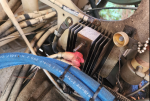
My PPD has seen better days. Studs are extremely rusted, and the top post might have twisted when I was removing the nut (I used a wire brush to knock rust off, let penetrating oil sit for 15mins+, and re-applied penetrating oil a few times to try and avoid this twisting. It either twisted in the middle of the stud, attempting to shear off, or twisted entirely in the base). I'm going to wire wheel the **** out of it and do some tests on my bench setup with multimeter, but it seems like this will only be more and more difficult to find. And was a pain to even get to.
1714057138687.png

I found some commercially available diodes I think might be decent in-cab replacements:

220CMQ030, which is a 30V 110A diode *pair*. Aside from having an extraneous input and an overly spec'd amp rating, seems pretty ideal. Could easily be mounted on a heatsink, but I *doubt* there's anywhere near 50A of 24v or 12v going into the cab despite the relays being rated for that on the back of my PDP... Two of these would be about $140 shipped, similar in cost to the used, unknown condition/untested, PPDs I see on eBay. 1/4-20 screw mounted (similar in size to M6, for future reference).

1714055781501.png

There are cheaper ones like this VS-T70HFL20S02, rated at 70A and 200V. Would probably fit pretty well behind the PDP and uses M5 screws (0.19")

1714056871043.png

There are double parallel diodes like this SK2S120-100, but it mounts with M4 screws (0.15")... which seem vastly undersized to interface with the 4-6AWG cabling I've seen behind the PDP ? Otherwise, 60A per diode, 100V max, seems reasonable.
1714056309499.png

Or this Amazon special LCLCTC 200A one, which I'm hesitant to use due to the terrible description but it appears to be a generic MD250 alieexpress/alibaba diode which have datasheets available. Mounts with M6 (or the 100A version mounts with M5). The only written review for this just expresses displeasure with the description being poorly translated. The 100A version has many other reviews, and this is just a generic diode sold under a dozen different names.

1714057226870.png

It seems like the PPD could then be upgraded to an LBCD with a Victron BatteryProtect 100A (or the "smart" bluetooth version Victron Energy Smart BatteryProtect 100A). Could anyone think of why this would, or wouldn't, work ? Batt/Alternator cable combined with cab 12 or 24v cable -> Battery Protect -> Diode -> PDP ?

It is a shame the battery protect doesn't incorporate a diode into it.
Danger Reverse Current when using Battery Protect for charging - Victron Community (victronenergy.com)

1714049393940.png

Thoughts ?
 
Last edited:

MatthewWBailey

Father, Husband and Barn Hermit
Steel Soldiers Supporter
378
884
93
Location
Mesa, Colorado
but could it be providing reverse current protection to the alternator or suppressing voltage spikes from 12v/24v cab circuitry
I don't know how this could possible happen if batteries are connected. There's no real power sources in the cab circuitry even when the blower is coasting to a stop. Plus the alt is diode-protected to begin with, which is why no current flows in reverse from the batteries when the engine is off, on any vehicle. My new alt has a test spec on reverse "leakage current" of 1ma max, (prob the remote sense circuit).

off grid solar installs are a different animal bc you have the risk of house fire, so the added insurance of a BP is worth it. The BP protects the little, puny charger from 100s of batt amps, if it fails. That's it. On a vehicle, the alt doesn't need reverse polarity protection, but the cab circuitry and ecm's do against an idiot reversing the batt leads on jumping or mistaken assembly.

As is well documented, I removed all that crap, relay, LBCD. Check the wiring twice and it's not a concern. Everything runs swimmingly wo all that sh!t. But then again, I trace out my batt leads if I work on them.

I ask the forum in general why no other cars or trucks have these things? Or do they and I've not seen it? Seems like a lot of equipment to protect against the actions of an inexperienced operator.
 
32
89
18
Location
NC
I don't know how this could possible happen if batteries are connected. There's no real power sources in the cab circuitry even when the blower is coasting to a stop. Plus the alt is diode-protected to begin with, which is why no current flows in reverse from the batteries when the engine is off, on any vehicle. My new alt has a test spec on reverse "leakage current" of 1ma max, (prob the remote sense circuit).

off grid solar installs are a different animal bc you have the risk of house fire, so the added insurance of a BP is worth it. The BP protects the little, puny charger from 100s of batt amps, if it fails. That's it. On a vehicle, the alt doesn't need reverse polarity protection, but the cab circuitry and ecm's do against an idiot reversing the batt leads on jumping or mistaken assembly.

As is well documented, I removed all that crap, relay, LBCD. Check the wiring twice and it's not a concern. Everything runs swimmingly wo all that sh!t. But then again, I trace out my batt leads if I work on them.

I ask the forum in general why no other cars or trucks have these things? Or do they and I've not seen it? Seems like a lot of equipment to protect against the actions of an inexperienced operator.
That all checks. It really is that last part that has me going "hm... what are we missing ?". I was talking with an old radar maintainer who works for us about this, and he had a little chuckle and went "I wonder if, during their initial prototype/proof of concept phase, someone had a whoopsie and it became a design element".

I have considered that with car batteries, they are an asymmetric shape (for the most part) and reversing the leads would be difficult with battery lead length being exactly long enough to reach only one terminal, in one orientation, for $$$ reasons. With the spacious battery box, no need to make a profitable vehicles for gov, and the symmetry of the 6T, it might be easier to incorrectly connect ? Perhaps early on/prototypes they had copper battery cables that could be hooked up either way due to length. Little-big whoopsie and now we have steel cables that really only want to be hooked up one way, with a PPD ? I'm also curious why I could stab someone with the cables from PPD to batteries... I have never seen steel battery cables before.

I don't know. Conjecture.

I forget which forum post(s), might have been yours, but I'm leaning heavily towards eliminating it and making a system similar to what is in my other truck/most vehicles... Run 2/0 straight from alternator to two 600A busbars in the battery box and 200A fuses (MEGA/AMG or MBRF), then running 4AWG from cab to said busbar via BSS 285 series 50A thermal breaker on the 12v and 24v side with a Blue Sea Systems 5510E e-Series Dual Circuit Battery Switch and/or ML-RBS with switch in the cab to kill power for maintenance and security through complication (lol).

This would also help prep for adding a habitat on the back charged from the alternator, or upgrading to 200A alternator, or moving to a straight 24v commercial higher-amp alternator.
 

MatthewWBailey

Father, Husband and Barn Hermit
Steel Soldiers Supporter
378
884
93
Location
Mesa, Colorado
That all checks. It really is that last part that has me going "hm... what are we missing ?". I was talking with an old radar maintainer who works for us about this, and he had a little chuckle and went "I wonder if, during their initial prototype/proof of concept phase, someone had a whoopsie and it became a design element".

I have considered that with car batteries, they are an asymmetric shape (for the most part) and reversing the leads would be difficult with battery lead length being exactly long enough to reach only one terminal, in one orientation, for $$$ reasons. With the spacious battery box, no need to make a profitable vehicles for gov, and the symmetry of the 6T, it might be easier to incorrectly connect ? Perhaps early on/prototypes they had copper battery cables that could be hooked up either way due to length. Little-big whoopsie and now we have steel cables that really only want to be hooked up one way, with a PPD ? I'm also curious why I could stab someone with the cables from PPD to batteries... I have never seen steel battery cables before.

I don't know. Conjecture.

I forget which forum post(s), might have been yours, but I'm leaning heavily towards eliminating it and making a system similar to what is in my other truck/most vehicles... Run 2/0 straight from alternator to two 600A busbars in the battery box and 200A fuses (MEGA/AMG or MBRF), then running 4AWG from cab to said busbar via BSS 285 series 50A thermal breaker on the 12v and 24v side with a Blue Sea Systems 5510E e-Series Dual Circuit Battery Switch and/or ML-RBS with switch in the cab to kill power for maintenance and security through complication (lol).

This would also help prep for adding a habitat on the back charged from the alternator, or upgrading to 200A alternator, or moving to a straight 24v commercial higher-amp alternator.
Agreed on the cables. They can easily be landed on the wrong terminals.

That sounds clean. I just deleted things and added 12v victrons from x1 to x2.
here is my edited Fmtv schematic...

79CECF1F-6AA3-479E-A263-E3F7D856D0A2.png0FB964EF-B49A-464D-9725-84790F31DE07.jpeg
 

coachgeo

Well-known member
4,976
3,342
113
Location
North of Cincy OH
I have a 2002 M1078A1 (really an A0.5 since no batt disconnect and has the Polarity Protection Device vs the Load Balancing Control Device). ...

View attachment 921871
...

Thoughts ?
since the name of the LBCD in itself carries the reader into some thoughts on its function we need to use the right name (a mistake I made many times myself.... but recent clarity slapped myself back to reality lol)...... the "B" in LBCD is not "balance" it is just "battery" . there is no "balancing" feature of that device.

Otherwise..... GREAT THREAD.
 

coachgeo

Well-known member
4,976
3,342
113
Location
North of Cincy OH
...

I ask the forum in general why no other cars or trucks have these things? Or do they and I've not seen it? Seems like a lot of equipment to protect against the actions of an inexperienced operator.
do believe most all modern vehicles have them but few know it for reasons mentioned about the cable length to hook up batts typically forces reality of hooking a batt up right..... and jump starting newer cars does not happen often enough for the problem to occur with enough frequency to hit the airwaves, blogs, discussions with much frequency either.

Had a 2003 vw TDI with one but no one knew it (at that time I'd never heard of such a beast either) .. it blew after my foolishly Ietting a fella hook up jumper cables to his car, to jump mine (he did them backward). Car would not start run again after that... forums, mechanics etc.... could not figure out why.

....took a year and sadly trading the non starting/running one away to a TDI mechanic for a more used TDI that ran with twice the miles on it.... (I HAD to have a car). He found it........ a main blow PDP unit under the driver seat of all places was blown. swapped it out and whala..... he got a basically new car. (this was back in early 2000's )

Otherwise..... modern vehicles also put a rev. polarity on about every add on device too..... car stereos have their own for example.
 
Last edited:

Ronmar

Well-known member
3,285
6,632
113
Location
Port angeles wa
1. The A0 PPD is simply diodes and a heat-sync. the alternator does NOT go thru the PPD, it simply connects to the battery cables on the PPD 12 and 24v BATT terminals. The combined output of the ALT/BATT system(those 2 work together), passes thru the diodes to reach the main power panel.

2. The LBCD has the same diodes, and adds two more circuits.
A. One circuit to monitor alternator voltage and RPM and control the disconnect relay at the batteries, and control the dash charge trouble light according to its programming.
B. The second circuit is a LARGE capacitor bank(about half of the LBCD case is occupied with caps).

When you disconnect a running alternator from its load, its output voltage spikes because it takes a bit for the regulator to detect the increase voltage and reduce the field excitation. then it takes a little more time for the field to actually collapse after the field current is reduced. With no or reduced load to absorb the full output of the alt, the voltage spikes.

The capacitors are intended to try and catch this spike, which unabated can easily reach into the hundreds of volts...

It is generally considered to be a VERY bad idea to disconnect the battery/load stabilizer from a running alternator because of this. I think you would be hard pressed to NOT find this caution in any automotive maintenance or electric manual. These knuckleheads added a circuit to this system that does it deliberately...

The LBCD was a really bad idea of a Band-Aid to protect a very expensive undersized alt from a grossly oversized battery, instead of properly matching these two components of an electrical system like EVERYONE else who produces vehicles does.

I would NOT deliberately plan any system that could disconnect the alt from the batteries... You do however really need to properly size the batteries for your alternator. Our dual volt alts, when pulling full load out of the 12v side, loose 1/3 of their possible electrical output(1950W). A pair of 6T wet cells or a pair of group 31 wet cells are a good match for the 100A alt. A pair of group 27 in AGM is also a pretty good match for the dual volt alt.

A straight 24v only alt at 100A can sustain 2800W of output, so the 4 battery 6T bank in wet cell is a barely viable setup for a straight 24V alt.

AGM batts are looking for 45% more energy out of a alt when charging. That was what forced the producers to shift the later trucks to the 260A alt, even with the LBCD to protect it, the 100A alt just couldn't cope when they went to mostly AGM batteries.

Diodes are a good idea, particularly on the 12V lead, as if you loose the ground connection to the batteries, you can have reversed 12v flow thru anything on the 12v circuit if anything on the 24v circuit is turned on...
 
Last edited:
32
89
18
Location
NC
Agreed on the cables. They can easily be landed on the wrong terminals.

That sounds clean. I just deleted things and added 12v victrons from x1 to x2.
here is my edited Fmtv schematic...

View attachment 921877View attachment 921878
Nice setup, and thanks for the drive link to your diagram. Really like Victron stuff and plan to use "the blue stuff" during the build.

Working on a diagram in Visio right now to see how I think it should be, and will reference your diagram as well !
 

Ronmar

Well-known member
3,285
6,632
113
Location
Port angeles wa
do believe most all modern vehicles have them. My TDI 2003 did but no one knew it (at that time I'd never heard of such a beast either) .. it blew after Ietting a fella hook up jumper cables to his car to jump mine (he did them backward). Car would not start run again after that... forums, mechanics etc.... could not figure out why.

....took a year and sadly trading the non starting/running one away to a TDI mechanic for a more used TDI that ran.... (I HAD to have a car). He found it........ a main blow PDP unit under the driver seat of all places was blown. swapped it out and whala..... he got a basically new car. (this was back in early 2000's )

Otherwise..... modern vehicles also put a rev. polarity on about every add on device too..... car stereos have their own for example.
Exactly, Most all manufactures provide polarity protection at the individual electrical modules, with diodes on their input, they simply will not flow current backwards... Do the systems in the LMTV do this? That is anyone's guess without some research and testing... LED lights wont work backwards, and incandescent lights don't care:)

Alternators have diodes on their outputs, so will only flow current one way thru their stators.

with us tapping 12 out of the middle of 24, without PPD diodes in circuit, it is possible to "hook up" all the 12v circuits backwards simply by lifting the battery ground with one of the 24v systems turned on.
 
32
89
18
Location
NC
since the name of the LBCD in itself carries the reader into some thoughts on its function we need to use the right name (a mistake I made many times myself.... but recent clarity slapped myself back to reality lol)...... the "B" in LBCD is not "balance" it is just "battery" . there is no "balancing" feature of that device.

Otherwise..... GREAT THREAD.
Fixed good sir. Thanks for the correction !
 
32
89
18
Location
NC
1. The A0 PPD is simply diodes and a heat-sync. the alternator does NOT go thru the PPD, it simply connects to the battery cables on the PPD 12 and 24v BATT terminals. The combined output of the ALT/BATT system(those 2 work together), passes thru the diodes to reach the main power panel.

2. The LBCD has the same diodes, and adds two more circuits.
A. One circuit to monitor alternator voltage and RPM and control the disconnect relay at the batteries, and control the dash charge trouble light according to its programming.
B. The second circuit is a LARGE capacitor bank(about half of the LBCD case is occupied with caps).

When you disconnect a running alternator from its load, its output voltage spikes because it takes a bit for the regulator to detect the increase voltage and reduce the field excitation. then it takes a little more time for the field to actually collapse after the field current is reduced. With no or reduced load to absorb the full output of the alt, the voltage spikes.

The capacitors are intended to try and catch this spike, which unabated can easily reach into the hundreds of volts...

It is generally considered to be a VERY bad idea to disconnect the battery/load stabilizer from a running alternator because of this. I think you would be hard pressed to NOT find this caution in any automotive maintenance or electric manual. These knuckleheads added a circuit to this system that does it deliberately...

The LBCD was a really bad idea of a Band-Aid to protect a very expensive undersized alt from a grossly oversized battery, instead of properly matching these two components of an electrical system like EVERYONE else who produces vehicles does.

I would NOT deliberately plan any system that could disconnect the alt from the batteries... You do however really need to properly size the batteries for your alternator. Our dual volt alts, when pulling full load out of the 12v side, loose 1/3 of their possible electrical output(1950W). A pair of 6T wet cells or a pair of group 31 wet cells are a good match for the 100A alt. A pair of group 27 in AGM is also a pretty good match for the dual volt alt.

A straight 24v only alt at 100A can sustain 2800W of output, so the 4 battery 6T bank in wet cell is a barely viable setup for only 24V AGM batts are looking for 45% more energy out of a alt when charging. That was what forced the producers to shift the later trucks to the 260A alt, as they went to mostly AGM batteries.

Diodes are a good idea, particularly on the 12V lead, as if you loose the ground connection to the batteries, you can have reversed 12v flow thru anything on the 12v circuit if anything on the 24v circuit is turned on...
Thank you for taking the time to explain this in yet another thread !

Poor wording on my part, with "providing reverse current protection to the alternator or suppressing voltage spikes from 12v/24v cab circuitry ?" Two separate questions, which I edited in the original post.

Could it be providing reverse current protection to the batts/alternator (top post of PPD) ?​
And/or could it be suppressing voltage spikes (kind of via mis-use, since that is the purpose of capacitors) from cab components turning on/off ?​

Based on the above comments from coach and yourself, out of an abundance of caution, I think I'm going to incorporate the VS-T70HFL20S02 diode between the batt/alternator cable and the PDP. Either at the box or in the cab. I could always remove it.

I currently have 2 batteries in the truck but plan to move to 4 with a 28SI 24v alternator.

with us tapping 12 out of the middle of 24, without PPD diodes in circuit, it is possible to "hook up" all the 12v circuits backwards simply by lifting the battery ground with one of the 24v systems turned on.
That's a scary thought with how often I have disconnected the batteries in my 4mo of ownership...
 

MatthewWBailey

Father, Husband and Barn Hermit
Steel Soldiers Supporter
378
884
93
Location
Mesa, Colorado
with us tapping 12 out of the middle of 24, without PPD diodes in circuit, it is possible to "hook up" all the 12v circuits backwards simply by lifting the battery ground with one of the 24v systems turned on.
That's why I deleted that center 12v tap. It's the equivalent of a floating neutral on a 240/120 system, prone to wild voltage swings. Poor design choice imo. I guess I could still add a diode set to the manual disconnect for overkill.
 

Ronmar

Well-known member
3,285
6,632
113
Location
Port angeles wa
yea using a 24-12 converter mostly removes the need for the diodes. it in itself is polarity protected, so if 24v is hooked up backwards it wont output 12 anyway...

On the A0, you need 12v to turn on 24v ign, so that only leaves the 24v circuits that receive batt power directly in potential peril from a misconnected battery...
 
32
89
18
Location
NC
yea using a 24-12 converter mostly removes the need for the diodes. it in itself is polarity protected, so if 24v is hooked up backwards it wont output 12 anyway...

On the A0, you need 12v to turn on 24v ign, so that only leaves the 24v circuits that receive batt power directly in potential peril from a misconnected battery...
I wonder if it is still that way on the early A1 trucks...

I know the answer to this is to investigate and find out, but haven't put the time into that yet.


Went ahead and ordered 3 of those diodes (so I can torch one).

I think this is more or less how I want to do it. I'll cross the balancer/equalizer road when I get to it, but should make this slightly cleaner.

EDIT: added disconnect

1714069795200.png
 
Last edited:

Ronmar

Well-known member
3,285
6,632
113
Location
Port angeles wa
no, all the A1 trucks(green circuit board power panel or PDM boxes) have both 12v and 24v ignition relays located under the panel frame. your A1 has 4 bolt heads visible on the A1 panel, 12v batt, 24v batt, 12v ign and 24v ign. Myself personally I would do away with the PPD and put the diodes at the input to the power panel 12 and 24v battery connections. you do still need to tie batt, alt and cab cables together at some point, like where the PPD is, but that is still a lot of connections out in the weather, which has proven problematic for these trucks... i did a vid on my utube channel on my 24v conversion, showing how I changed my wiring. username; Rronmar...
 
Last edited:
32
89
18
Location
NC
no, all the A1 trucks(green circuit board power panel or PDM boxes) have both 12v and 24v ignition relays located under the panel frame. your A1 has 4 bolt heads visible on the A1 panel, 12v batt, 24v batt, 12v ign and 24v ign. Myself personally I would do away with the PPD and put the diodes at the input to the power panel 12 and 24v battery connections. you do still need to tie batt, alt and cab cables together at some point, like where the PPD is, but that is still a lot of connections out in the weather, which has proven problematic for these trucks... i did a vid on my utube channel on my 24v conversion, showing how I changed my wiring. username; Rronmar...
And you also did an update to it ! And have returned your cooling system to something more commercial with your 3116.

I'm a huge fan and have learned a lot from your posts, so thank you.

The diodes may be in the cab, or the battery box. Depends on what seems like the cleanest install location. They should get here this week.

V1.1 of phase 1... which is to redo the cables to/from the PPD. Phase2 will be to incorporate a vanner or some kind of 24v converter and no longer take 12v from the batteries, just send 24/12v from alternator to the bank, then converter to the busbar.. I'm going to make a new 2/0 cable from alternator 24v to the battery box busbar since the 1/0 on it is not really rated for more than 150A at that distance per this 12v ampacity chart and I'd rather have a new cable for future proofing. The 12v will be butt spliced with a hydraulic crimp connect and dual wall marine heatshrink. The 12v and 24v cab feed cables will also be hydraulically crimp spliced to extend to the battery box bus bars.

That Blue Sea Systems 5510E e-Series Dual Circuit Battery Switch is rated for 1000A for 10sec, 750A for 1min, and 350A continuous per circuit. I can't find the 3126 starter specs, but the C7 "upgraded" starter is 7.8kW @ 24v, or ~325A. Even if my voltage drops to half (ridiculous) during cranking and it pulls 750A, the switch will be fine.

I'll use a 600A busbar on the 24v side and a 150A busbar on the 12v side.

1714182233666.png
 
32
89
18
Location
NC
That's why I deleted that center 12v tap. It's the equivalent of a floating neutral on a 240/120 system, prone to wild voltage swings. Poor design choice imo. I guess I could still add a diode set to the manual disconnect for overkill.
Found all of your 28SI alternator posts here:


Pretty much the exact setup I was searching for. I will be knocking that off completely if/when my 100A Neehoff dies. Hoping to extend its life a bit by running a 24v setup only, but I am getting some voltage spikes on the trans currently as I mentioned in first post...

I tried searching your posts but didn't see any reference, what year/make is your truck ? A1 or A1R ?
 
Top
AdBlock Detected

We get it, advertisements are annoying!

Sure, ad-blocking software does a great job at blocking ads, but it also blocks useful features of our website like our supporting vendors. Their ads help keep Steel Soldiers going. Please consider disabling your ad blockers for the site. Thanks!

I've Disabled AdBlock
No Thanks