• Steel Soldiers now has a few new forums, read more about it at: New Munitions Forums!

  • Microsoft MSN, Live, Hotmail, Outlook email users may not be receiving emails. We are working to resolve this issue. Please add support@steelsoldiers.com to your trusted contacts.


Dual Circuit Brake Engineering Thread

rustystud

Well-known member
9,071
2,388
113
Location
Woodinville, Washington
Pardon me for being a couple of years too late, but do you know of any sources for the split circuit master cylinders w/reservoir for the USAF M35s?
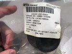
First download the retrofit document in the deuce download section. You will also need to buy another air-pac. The brake lines are easy to make up yourself. Peashooter (Aaron) has a sticky on parts.
 

peashooter

Well-known member
1,039
204
63
Location
Hanover, minnesota
CAD File for Master Cylinder Bracket

Well Clinto was able to obtain a new Dual Circuit Master Cylinder Bracket. We modeled it up in 3D CAD....and then ran out of time to put much additional effort into the project for the time being. We understand that this is a complex shape and not something likely to be easily duplicated at a cost inline with what most members are willing and able to pay. In an attempt to take advantage of the site's many members who may have creative ways to redesign this in a cost effective way and/or access to discounted manufacturing processes needed, we wanted to share what info we have put together so far (a digital CAD model of the factory bracket). So for you folks who have Fab skills, tools, and access to a CAD software; you can find the files on GRABCAD (a CAD fileshare site). The files are saved in a number of formats, but there are NO DRAWINGS, only 3D CAD files. The 3D files contain all the dimensioning needed.
Please note that the bracket was modeled exactly after the cast bracket. There is a "Simplified" version cad file of the bracket as well that has most of the fillets and drafts removed that are inherent to the cast design. The model should at least give proper dimensions and angles for those who undertake the challenge of redesigning this into an easier to fabricate weldment that will meet form, fit, and function of the original ductile iron casting.
The files can be found here: https://grabcad.com/library/m35a2-du...nder-bracket-1

If anyone finds a good way to reproduce this, be sure to share pics of it!

MC BRACKET ASSY PIC 1.jpgMC BRACKET ASSY PIC 2.jpgMC pic 3.jpgMC pic 2.jpgMC pic 1.jpgView attachment bracket pdf.pdfView attachment TM Diagram Pics.pdf
 

A Blind Man

Member
Steel Soldiers Supporter
47
9
8
Location
Canton, OH
Quick question in regards to the rubber boot that fits around the end of the MC, Does it fit into the c-bore on the bracket or does it just stick into the bore of the MC in front of the C clip?

relatedly before I go finding a random MC boot and adapting it, is the boot a stock part or a custom bastardized fit?


EDIT: Man that search feature can be useful sometimes...
I figured this one out on my own.

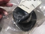
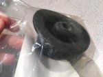
Just loosen the four MC mounting bolts (without removing the bolts or the MC). Push the wide end of the boot back in between the MC and mounting base... (give it a few spins to make sure there is no kinks or binding), then re-tighten the four bolts.

There is a recess for the boot to rest in between the master cylinder and mount, and it fits perfect.

Anyway, that's that.
 
Last edited:

peashooter

Well-known member
1,039
204
63
Location
Hanover, minnesota
Quick question in regards to the rubber boot that fits around the end of the MC, Does it fit into the c-bore on the bracket or does it just stick into the bore of the MC in front of the C clip?

relatedly before I go finding a random MC boot and adapting it, is the boot a stock part or a custom bastardized fit?


EDIT: Man that search feature can be useful sometimes...

Also its the same boot used on the A3 trucks. I've bought some off ebay a few times. Here are some pictures...
 

Attachments

jkcondrey

Active member
Steel Soldiers Supporter
317
140
43
Location
Rutherfordton, NC
I have been pondering this brake issue for some time now, since getting my deuce actually. I have replaced all lines and wheel cylinders in hopes of keeping it as safe as possible. But I have thought about how to do this differently. Maybe some hydraulic expert could chime in on my idea. Similar to how a proportioning valve works, couldn't it be possible to make a valve that would only allow so much fluid to go through with the hardest braking pedal pressure possible by a driver? If this amount could be determined, why not create a valve that would sense the excess fluid flow and shut that line down automatically? Or maybe have it so that it is similar to a shock with hydraulic fluid in it, allowing only that predetermined maximum flow to go through. It would still leak from a failure but would give you more time to get to a stop before losing all fluid. Maybe it could be wired to fire up a brake light if the line went out too. Hopefully I haven't missed this theory someplace else already.
 

A Blind Man

Member
Steel Soldiers Supporter
47
9
8
Location
Canton, OH
I have read about "fuses" in larger systems but surely it can be scaled down to brake lines??
The use of hydraulic fuses like in airplanes has been discussed in another thread I believe. The main issue is the extremely small amount of fluid/flow rate

Looking at proportioning valves, at least here in the steel mill, out cheapest proportioning valves are in the 1k+ range, and nowhere near what would be needed in this case...
also you would essentially need to put one per axle or one per wheel or however you wanted to divide it...

What Would almost be better would be to put isolation valves on each axle (or at various points on the line) 24v close, spring open, and when you discover a brake failure (if time allows) isolate various portions of the circuit with a set of switches.
 

rustystud

Well-known member
9,071
2,388
113
Location
Woodinville, Washington
I have been pondering this brake issue for some time now, since getting my deuce actually. I have replaced all lines and wheel cylinders in hopes of keeping it as safe as possible. But I have thought about how to do this differently. Maybe some hydraulic expert could chime in on my idea. Similar to how a proportioning valve works, couldn't it be possible to make a valve that would only allow so much fluid to go through with the hardest braking pedal pressure possible by a driver? If this amount could be determined, why not create a valve that would sense the excess fluid flow and shut that line down automatically? Or maybe have it so that it is similar to a shock with hydraulic fluid in it, allowing only that predetermined maximum flow to go through. It would still leak from a failure but would give you more time to get to a stop before losing all fluid. Maybe it could be wired to fire up a brake light if the line went out too. Hopefully I haven't missed this theory someplace else already.
There is no "cheap" way to isolate any leaking wheel cylinder or broken line. By the time you realize the brake line is broken all the fluid would be gone. That is why the "hydraulic Fuse" would not work. The only thing you can realistically do, is keep spare brake fluid on hand and extra rubber lines for the front and rear axles and a good set of vise grips to "crimp" the steel lines if they break or leak. Of course that doesn't help when your trying to stop ! So keep up on your maintenance so you don't have a failure on the road.
 

kswilsher

New member
12
0
1
Location
Tulsa/OK
The simple fact is a hydraulic fuse is set off when large amounts of hydraulic fluid passes by. A brake system moves a very small amount of fluid at a time so how would the fuse detect the difference between a leak and an application of brakes. 31 years aircraft mechanic, so I know a little about this. Also, I have never seen an aircraft with a hydraulic fuse in it's brake system, just the main hydraulic systems.
 

A Blind Man

Member
Steel Soldiers Supporter
47
9
8
Location
Canton, OH
I believe this has been confirmed in a different post by peashooter way back when, (having trouble finding it again though) But just to verify only the A3 master cylinder needs the larger front wheel cylinders, the air force A2 master with the reservoir on the master uses the standard ones?
 

rustystud

Well-known member
9,071
2,388
113
Location
Woodinville, Washington
I believe this has been confirmed in a different post by peashooter way back when, (having trouble finding it again though) But just to verify only the A3 master cylinder needs the larger front wheel cylinders, the air force A2 master with the reservoir on the master uses the standard ones?
That's correct. Though you can use the larger wheel cylinders on the front of a M35A2 deuce.
 
Last edited:

zanther

Member
158
2
18
Location
Maltby, WA
I'm working through the quote process with a small foundry here in Seattle to make replacements Split Circuit stock master cylinder bracket. Using Peashooter and Clinto's reference files and maybe I'll pull my bracket off my truck for reference as well. I've asked for an quote with an initial run of 50. I don't know the cost yet and know that demand will largely depend on price point.

I don't see a poll option, so PM me if you'd be interested in a bracket(s).

Also of note, we might be able to get these cheaper if we removed the dog ear for the PTO lever. Let me hear your thoughts on that too.

Cheers,
Melvin
 

zanther

Member
158
2
18
Location
Maltby, WA
Just heard back from the Foundry, it's 10K in tooling costs. + the actual casting work. He hasn't given me a quote on casting +machining yet.

Before I have him go further, I need to gauge interest. if these cost $400-$500 each to make, would you buy one? That'd be cast, machined, tap'ed. I'm not looking to make money so it'll be a straight split on the total cost of the initial run.
 

m715

Member
237
16
18
Location
western ma.
I had bid on a complete used master cylinder, with mount and break peddle plus line set up last week on a auction site. The item sold for more than $300.00. I don't know if that info helps you but at least one person paid that amount.
 

SP5

Member
75
2
8
Location
scappoose, oregon
Could the file(s) from Peashooter and Clinto be fed-into a 3D printer,,? If so, could not the printer produce a part that could be used as the actual pattern for a casting,,?
I don't know much about such things,, a good friend of mine is a long time pattern maker, perhaps I should talk to him about the process.
Just thinking,,.
 

goodwithwood35

Active member
Steel Soldiers Supporter
327
51
28
Location
Bakersfield, CA
Could the file(s) from Peashooter and Clinto be fed-into a 3D printer,,? If so, could not the printer produce a part that could be used as the actual pattern for a casting,,?
I don't know much about such things,, a good friend of mine is a long time pattern maker, perhaps I should talk to him about the process.
Just thinking,,.
Yes...as soon as my 3D printer is working again I will be printing this


Sent from my iPhone using Tapatalk
 

A Blind Man

Member
Steel Soldiers Supporter
47
9
8
Location
Canton, OH
I had bid on a complete used master cylinder, with mount and break peddle plus line set up last week on a auction site. The item sold for more than $300.00. I don't know if that info helps you but at least one person paid that amount.
Was that an airforce unit? I know you can get a NOS cylinder/reserviour alone for abouts 150...
 
Top
AdBlock Detected

We get it, advertisements are annoying!

Sure, ad-blocking software does a great job at blocking ads, but it also blocks useful features of our website like our supporting vendors. Their ads help keep Steel Soldiers going. Please consider disabling your ad blockers for the site. Thanks!

I've Disabled AdBlock
No Thanks