Big69C20 Toy
New member
- 10
- 0
- 1
- Location
- Roscoe, IL
Okay folks i've been lurking here for a while and reading where i can. I picked up my '86 M1009 in 2011 down in TN and it's been a barrel o' monkeys ever since. This post might be a bit lengthy but i'm doing my best to describe things and man do i hate electrical stuff.
Drove her home and since i got back to MI it's been one thing after another. Was having electrical gremlins and did the Doghead starter relay after my one fusible link lit up like a sparkler and wouldnt let 'go'. That time it took my starter out (had it repaired) and since then no trouble. I'd replaced several of the fusible links off the Pos terminal with fuses (yes i realize now a no-no).
Recently I was having more electrical gremlins with no brake lights and decided to get the thing rewired with a painless kit. Being deathly afraid and incompetent (mostly) with wiring on vehicles i took it to a mechanic to get it done.
Before i took it in aside from the brake lights being out all other systems were okay. Got it rewired and it was doing some slow cranking- mechanic thought it a weak battery. Batteries are Optima red-tops and are 1 yr old each. Tested batteries and they are good, took starter in and found the attenuator (sp?) was bad and threw solder all over the guts. Bought a new starter and still same thing. Replaced the starter cable and figured well i should just do them all.
Now i have 2ga wires from: starter to terminal, batt 1 to ground terminal, batt 2 to pos terminal, batt 2 to batt 1. Still no good cranking speed but she fires up. All those lines are copper terminals crimped then soldered and heat shrink tubing around joints.
Now here's where i think i jarred something up- i take off wires again, check the terminals and reconnect. When i was putting the wire back to the 12v (rear batt pos neg position) to the engine block (12V) i put it on the + terminal of the rear batt (24V).
Truck fired up like a dream then i go to shut it off and she wont shut down... so i disconnect the grounds on front batt/#1. She shuts down. hmm i think, weird. It's never had the shutdown issue ever. I check the wires again and fix the issue - moving that wire to the 12V (batt 2 - terminal).
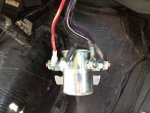
One thing i notice here when i reconnect the system; when i put either that 12V eng block wire on or the grounds to complete the system the starter relay (big 200A feller) it gives a big "thunk". It's never done that before even when cranking i never heard it (perhaps because the 6.2 is so loud).
Again she cranks slow as a dog but fires up. Now when i go to shutdown she wont die. Pull the grounds off bat 1 and she keeps going! Squeeze the tube and down she goes.
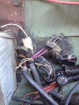
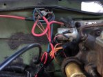
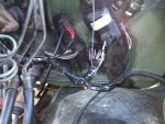
Now here's what i'm seeing when i check wiring.
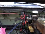
1) Starter Relay with ignition in off; Red=12v, purple=12v, purple/white=12v. Same combination when the ignition goes to run or to start.
2) Pink wire on fuel pump shut down solenoid is showing 12V whether the truck is in ignition positions Off/run/start etc.
3) Starter has 24V+ on the big post and the purple starter solenoid line is getting 12V when keyed to start. I used the starter housing as ground during my check so that should have meant grounding through the block was fine.
I don't have the starter tail/support bracket on the starter- my truck never had one but i know i should/will find one.
Ahah methinks- something went wrong because that shutdown solenoid should only be "hot" when in start or run. I check that solenoid for the 'thunk' with voltage on/off and it's good. I fire up truck and again it wont shut down so i yank that connector and down she goes. Also the "door lock" fuse popped. I replaced it with another 20A.
Now the truck still cranks slow and wont shut down. Batteries i've had tested 2x each- both showing good though the 1st round i did see one battery at 90% and the other at 35% (rear was lower). I trickled them up for a couple nights then tried cranking again but same issue on slow crank. 2nd battery test showed 93% and 98% but i cant recall which was which.
So i'm thinking i torched my starter relay and possibly other things. I'm all ears ladies and gents so please educate me... I did do some wire tracing by splicing open my new harness so if that level of information is needed i can give it. (IE that doorlock fuse is part of the circuit going to my red starter relay line).
I probably am missing lots of 'brainless' items like shouldnt that red starter relay be 24V? Shouldnt the starter relay only show the red line hot until the ignition is put to start (IE purple/white closes the circuit to purple)?
Thanks all!
Last edited:


