• Steel Soldiers now has a few new forums, read more about it at: New Munitions Forums!

  • Microsoft MSN, Live, Hotmail, Outlook email users may not be receiving emails. We are working to resolve this issue. Please add support@steelsoldiers.com to your trusted contacts.


Fast Axles

m-35tom

Well-known member
Supporting Vendor
3,021
220
63
Location
eldersburg maryland
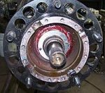
OK so these are not planetary but spider gears like in the diff. Could planetary be installed in place of this whole setup? Why not?
 
Last edited:

scottmandu

Active member
822
35
28
Location
Texas
does the FMTV have portal axles? Can you change the gears in the hub? I can have gears made pretty cheap.
The axles are a bevel gear reduction on the wheel end, not portals. Regardless of bevel gear size the reduction will always be 2:1 unless they are eliminated.
 

coachgeo

Well-known member
4,970
3,340
113
Location
North of Cincy OH
It has been questioned that maybe a manual hub could be developed to manually remove the hub reduction when choosing too. Also one can remove the reduction by welding the gears. but either one brings up issues

. can axle components withstand this? In hub gears be it portal or just hub reduction like these trucks.... lessons strain on R&P as well as axle shafts and lockers etc. without the gears in hub ..... what issues arise further up stream? Look at how small the thirds are in these trucks compared to trucks of same size with out portal or hub reduction.. in comparison they are tiny. IMHO they could make the thirds etc. smaller due to the in hub gears.

. without access to first gear in tranny (or maybe better said... without Allison or someone providing new software opening access to first gear in AWD) can the truck even move from stop in AWD with an overall higher overall ratio (same holds true for anyone looking into machining new R&P)
 
Last edited:

m-35tom

Well-known member
Supporting Vendor
3,021
220
63
Location
eldersburg maryland
The axles are a bevel gear reduction on the wheel end, not portals. Regardless of bevel gear size the reduction will always be 2:1 unless they are eliminated.
Hi, sorry that is not always true. The ratio is that of the drive gear and the fixed gear. So the axle drives a bevel gear and there is a fixed gear on the axle housing with spider gears fixed to the hub. If the 2 gears involved are both 24 tooth like I think, it will be 2:1 reduction and turn in the same direction. I have heard other ratios but since I have not seen and counted myself I reserve comment. Further research is needed if increasing the drive gear by 1 tooth and reducing the fixed gear by 1 would be enough or maybe 2 is needed. Many things can be done, nothing is impossible.
 
Last edited:

DiverDarrell

Member
Steel Soldiers Supporter
629
21
18
Location
Port orchard, WA
BFE37797-B83B-49D2-AF45-222920957E1B.jpgHere is a photo of the reduction gears in the hub. Reduction is due to the ratio of the spider gears to the input/output gears. To change the reduction you change the spider gear size. The top input and the bottom output gears have to be the same size or it all bindes up. Without a complete change of the hub design there is no room for larger spider gears for a higher wheel speed vs input shaft speed. With the fmtv spindle and hub combo, your stuck at 2:1 in the hub. It’s not like a true planetary where you can change the input and sun gears to change final ratio.
 

m-35tom

Well-known member
Supporting Vendor
3,021
220
63
Location
eldersburg maryland
I don't yet agree that it would bind up, why would it? It may be that the 2 gears would need to have both even numbers of teeth.
OK I am not sure this will not work, you have a driven gear and a fixed gear with the spider gear assembly fixed to the hub. If you increase the driven gear and decrease the fixed gear by the same number of teeth it will not bind up, and you change the ratio right? Is there room? How do you compute the ratio in a setup like this? Assume you have 26 tooth driven and 22 tooth fixed. Is it 1.69:1? Which makes axle drive from 7.8 to 6.59?
 

DiverDarrell

Member
Steel Soldiers Supporter
629
21
18
Location
Port orchard, WA
Look at it like this. If the input gear, the top one is different in diameter than the output, then how would the spider gears mesh between the two. They are on a fixed diameter. Adding teeth to the input and not the output puts them physically out of alignment. The only way to change gear ratio in this system is to change the spider gear size. Doing that would require new spindles new hubs, and honestly it would be easier to change the output of the trans to divorce the transfer case and put in an air selectable transfer case.
 

m-35tom

Well-known member
Supporting Vendor
3,021
220
63
Location
eldersburg maryland
spider gear size has nothing to do with the ratio, that is set solely by the 2 large gears. how much larger does adding 2 teeth to a already 24 tooth gear make it? yes they would contact different areas of the spider gears, I just don't know it there is room or not.
 

DiverDarrell

Member
Steel Soldiers Supporter
629
21
18
Location
Port orchard, WA
Now you really got me thinking and a re look at the parts. Ok power comes in and drives one of the big gears. This in turn drives the 4 smaller gears on the cross. Now the cross is fixed to the hub that and provides power. The second big gear is fixed to the spindles with splines and does not rotate at all. So the smaller gears are what rotate the hub. Both the big gears have the same number of teeth. It’s the gear ratio between the big gears and the small gears the derive reduction.643AF8F8-C126-4AD4-8872-A55215163F3E.jpg 
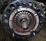
https://www.steelsoldiers.com/showthread.php?144834-M1078-LMTV-planetary-hub-setup. Has photos of it all installed
 

tennmogger

Well-known member
Steel Soldiers Supporter
1,576
527
113
Location
Greenback, TN
The axles are a bevel gear reduction on the wheel end, not portals. Regardless of bevel gear size the reduction will always be 2:1 unless they are eliminated.
Agree. The 2:1 ratio is that of 'diameter' to 'radius' and is constant. The actual diameter does not matter, nor does number of teeth. The teeth simply couple the "spider" gears to the end plates, allow them to transfer torque, and could be any size.
 
Last edited:

tennmogger

Well-known member
Steel Soldiers Supporter
1,576
527
113
Location
Greenback, TN
Agree. The 2:1 ratio is that of 'diameter' to 'radius' and is constant. The actual diameter does not matter, nor does number of teeth. The teeth simply couple the "spider" gears to the end plates, allow them to transfer torque, and could be any size.
I should have added IMHO preceding my comments. I have been wrong before. :) Thanks for pointing that out Tom.
 

m-35tom

Well-known member
Supporting Vendor
3,021
220
63
Location
eldersburg maryland
well I think number of teeth is important but this can not be thought of as normal gear ratios. if the driven gear was 26 teeth and the fixed gear was 22 teeth, the reduction ratio would be less than 2:1 but what would it be? and could it be done cheaper and easier than R & P swap? I also wonder about the ratios in the trans. what is the ratio in 7th speed? in a MD3060 it is .65 and is many times not programed in. changing 7th planetary in the trans may be easy. you only want 7th for hgwy use anyway. what is the diameter of a 1078 tire??
 

tennmogger

Well-known member
Steel Soldiers Supporter
1,576
527
113
Location
Greenback, TN
Guys, if Tom questions my logic, then I start questioning my logic. Maybe we should all question what we take as "facts". Do we know the ratio of the reduction hubs is 2:1?

That picture of the two end gears and the intermediate gear show a count of teeth of 14 for the intermediate gear, and 24 teeth for the end gears. That count is not arguable, is it? I went to the picture and counted them.

That's not a 2:1 ratio. For every rotation of the moving end gear, the shaft of the intermediate gears would move 0.58 of a revolution. 1:0.58 ain't 2:1. That gets the job done but it's not 2:1.

So based on Tom's suggestion, if two end plates and four intermediate gears "could" be fabricated, that "could" provide a faster ratio in the reduction gears. Now the problem, from the practical and $$$ standpoint, is that 24 new gears would have to be made. Not a practical solution to the speed problem.

But I have to include this bit of thought as to the 2:1 ratio derivation suggested. Tell me where I am wrong, please.

Here’s the logic I used. Tell me how I am fooling myself.

The gear set has this gear sandwich: 1) a fixed large gear splined to the spindle, 2) the ‘cross’ shaft with its four intermediate gears, and 3) a fast moving end gear driven by the axle coming through of the spindle.

The fast moving end gear forces the four intermediate gears to roll against the fixed gear, and their shaft’s rotational speed is half the rotational speed of that of the end gear. Since the intermediate gears shafts are the ‘cross’, and the cross drives the hub and wheel, therefore the wheel drives at half the speed of the axle.

That’s a 2:1 ratio. The end gears have to be the same size and the intermediate gears can be any size and roll between them. How can the physics of the rotational speed reduction be other than 2:1?

Think of a tire on a wheel as an analogy: Roll the tire by pushing on the tread at the top, and move that place on the tread by 1 foot. How far does the center of the wheel move? 6”, half the distance. The ratio of tire diameter to its radius is 2:1.

That applies to the intermediate gears. Fix one surface stationary. Push on the fast moving side of the intermediate gears and how far does their axle go, half as far. 2:1 ratio.

I still think this makes sense.

Respectfully submitted,
Bob

Edit: PS, ISN"T THIS FUN!
 
Last edited:

m-35tom

Well-known member
Supporting Vendor
3,021
220
63
Location
eldersburg maryland
This is fun!! The issue for many is that they think of the 14 tooth spider gears as having some bearing on the ratio, they don't, they are just there to compliment the 2 big gears. Now this is where we need someone clever with a 3D printed and a CAD / CAM program to make some plastic gears. BUT having said that, this is not going to be a cost effective solution, these bevel gears are very specialized and few companies can make them. I think the real solution is in the transmission. Need a lot more research on that. I need the serial number from the MD3070PT in a M-1078 to proceed with that, anyone??
Tom, a somewhat crazy almost scientist.
 

DiverDarrell

Member
Steel Soldiers Supporter
629
21
18
Location
Port orchard, WA
It’s been discussed on here in the past that the hubs may not be a true 2:1 ratio. A year or so ago I did a test where I put a degree wheel on a hub and rotated the drive to see what the true total reduction was. Hubs and diff and just hubs. But I don’t remember all the results, it’s posted on here someplace. Here is absolutely how the power is transmitted from the axle shaft to the hub.

from the diff the axle shaft runs out through the spindle through the attached to the spindle large gear that does not rotate, through the spider assembly to the outer large gear which it is attached via splines. The small gears are samwitched between the axle driven large gear and the fix non rotating (has pins in it to secure hub nut from rotating.) large inner gear. So as the large outer gear turns this causes the smaller gears to rotate and drive around the fixed inner large gear. This rotation action is captured via the cross that the smaller gears ride on. This cross is attached and fixed to the hub via the hub cap and hub, and the tires are attached to the hub.

FFF78186-CBDB-4E9E-A59C-126083532AF4.jpg
1. Hub with the hub but installed note the splines on the spindle, this is what the inner large gear goes on. The two pins on the hub nut that you can see go into two holes machined on the back of the gear. This is to secure the hub nut from moving(thing fancy castle nut and cotter pin). Behind the hub nut are the wheel bearings.

B5FD6686-3F25-4664-8212-BC205D19A8E9.jpg

2. This is the inner large gear now seated on the spindle splines. This gear can not rotate, as the spindle is bolted to the axle. The hub around it can rotate. They are not rotationaly attached yet. Notice the half cut outs for the cross the small gears ride on.

A6D3E02B-D8EA-410A-8FE5-4C51A26B7785.jpeg
3. Here you see the small grears on the cross. Nothing is attached to the drive axle yet, the drive axle is the splines you see still. Notice how the cross is sitting in the cutouts on the hub.

4. The outer large gear would be put on next, it’s splines would engage the drive axle. As the axle turns the outer large gear, which causes the small gears to spin. Since they are also in mesh with the fixed inner gear, it causes them to drive around the inner gear, and since the cross they ride on is captured by the hub, the hub is rotated as well.

I hope this this makes sense, you have to forgive me I’m a Boatswains mate chief in the USCG, and I’m used to explaining things in crayon, hopefully i didn’t eat it first. I’d explain this to non rates as Pure F’ing Magic, and why I had to see for myself

Here is from my rotation test a year ago

1984D880-C454-47AD-AA31-DDA41A823E65.jpg

I started at 0 and rotated the yoke on the diff until I got to 90. And made note of how much I turned the yoke. The yoke has a similar set up on it so I could repeat. Just had to keep count of rotations and final degree mark.

I took the cover off and the outer gear off. And did the same for the axle and rotated the yoke the same amount of times as before and got the following result.

B44AF6CE-FAEE-407A-8BB7-D7CA8898DBD7.jpg

I’m not sure on the how the 2:1 happens but I thing it has to do with the actual small gears rotating in relation to the fixed gear. Kind of like sun gears rotate around in a planetary set up.
 

Attachments

Last edited:

tennmogger

Well-known member
Steel Soldiers Supporter
1,576
527
113
Location
Greenback, TN
Nice pictures DiverDarrell, supporting your description. The 2:1 ratio results as described in post 75, and your description. The cross AXLE rotates half the speed of the fast gear rotation. The mistake is thinking normally about relative gear speed based on teeth number. This reduction does not care what the gear-tooth ratio is.
 
Top
AdBlock Detected

We get it, advertisements are annoying!

Sure, ad-blocking software does a great job at blocking ads, but it also blocks useful features of our website like our supporting vendors. Their ads help keep Steel Soldiers going. Please consider disabling your ad blockers for the site. Thanks!

I've Disabled AdBlock
No Thanks