• Steel Soldiers now has a few new forums, read more about it at: New Munitions Forums!

  • Microsoft MSN, Live, Hotmail, Outlook email users may not be receiving emails. We are working to resolve this issue. Please add support@steelsoldiers.com to your trusted contacts.


Fmtv no more dual voltage

Ronmar

Well-known member
3,184
6,477
113
Location
Port angeles wa
i think its the heat that kills it as it gets/ stays hot from trying to convert down to 12V from 24V all the time.

note: on battery equalization in a 24V system with two 12V batteries, the batteries are like two kids in a trench coat pretending to be a adult 24v battery.
So we have an upper(one you take 24V from) and a lower battery(the one connected to ground/chassis.)
In normal operation the voltage of both batteries should be equal. but when we take 12V loads(current) from the lower battery its voltage drops below that of the upper battery. With no equalization the 24V changing system doesn't see this imbalance and does nothing to fix it.
we add in a equalizer/dual voltage alt to bring the lower battery back up to an equal charge voltage as the upper battery. we do this by sending current back to charge the battery/provide current to loads so the battery it self doesn't need to do it. also if the lower battery voltage is higher than the upper no equalizer/dual alt can do anything about that and you need to either discharge via 12v loads or swap battery locations.

so technically you can treat the lower battery like a load and "charge" it with a Converter/Equalizer. this is why the bussman has the two different hook up methods.
Yea, we know the problems/complications with pulling 12 outta the middle of 24, that is why many of us are contemplating or are actually shifting to a straight 24v bank with converter...
 

Ohiobenz

Well-known member
Supporting Vendor
463
261
63
Location
Seville, OH
About 95% completed.
Waiting on the marine circuit breakers, 80A per 24v bank, 140A for the 12v was as close to Bussman specs as I could find, and 1 more terminal block for the 12v leg.
Bussman is installed, Smart Isolator is installed, battery banks are split, everything except for the 12v leg is wired up.
Alternator is installed - haven't figured out what to do with the wires off the regulator since this is an internally regulated and self-exciting unit.
Installing the radiator fan is next while waiting on the breakers to arrive.
 

Attachments

Ronmar

Well-known member
3,184
6,477
113
Location
Port angeles wa
About 95% completed.
Waiting on the marine circuit breakers, 80A per 24v bank, 140A for the 12v was as close to Bussman specs as I could find, and 1 more terminal block for the 12v leg.
Bussman is installed, Smart Isolator is installed, battery banks are split, everything except for the 12v leg is wired up.
Alternator is installed - haven't figured out what to do with the wires off the regulator since this is an internally regulated and self-exciting unit.
Installing the radiator fan is next while waiting on the breakers to arrive.
I would just insulate and tie the excitation and sense wires back To the wiring bundle they come out of. one has 24v on it when the engine is running, so you need to make sure it doesn’t find a connection to ground...
 

Ohiobenz

Well-known member
Supporting Vendor
463
261
63
Location
Seville, OH
I would just insulate and tie the excitation and sense wires back To the wiring bundle they come out of. one has 24v on it when the engine is running, so you need to make sure it doesn’t find a connection to ground...
Been trying to follow the A0 schematic rather unsuccessfully for those wires. How does the dash gauge get it's signal?
 

Ronmar

Well-known member
3,184
6,477
113
Location
Port angeles wa
Been trying to follow the A0 schematic rather unsuccessfully for those wires. How does the dash gauge get it's signal?
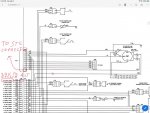
The dash gauge reads voltage from the power dist panel... neither of those wires On the reg goes to the gauge. One is 24v supplied from K11 to excite the alt once oil pressure is over 15PSI... the other wire runs to the STE connecter under the Drivers dash and is only used by the STE equip to monitor how hard the alt is working when testing the systems... I would just insulate and secure them...6ECA623D-92A9-4DB3-B957-7ECF281E782D.jpeg
 

Ohiobenz

Well-known member
Supporting Vendor
463
261
63
Location
Seville, OH
The dash gauge reads voltage from the power dist panel... neither of those wires On the reg goes to the gauge. One is 24v supplied from K11 to excite the alt once oil pressure is over 15PSI... the other wire runs to the STE connecter under the Drivers dash and is only used by the STE equip to monitor how hard the alt is working when testing the systems... I would just insulate and secure them...View attachment 809175
Thx.
So this is on foldout 7. On which page(s) do I find the continuation of that connector plug P31x ? At least P31 is labeled and tells me where things go. I just haven't figured out their schematic system yet.
I'm almost done doing the electric fan swap. Hope to fire it up today.


NVM... My smart wife picked up on the reference to the grid numbers.... it all makes sense now lol. As she said, I was stuck in the paradigm of prior schematics...
So if I disconnect 568A at K11 it would appear there is no other power going out that harness.
I've pulled the STE and it's harness some time ago.
 
Last edited:

coachgeo

Well-known member
4,929
3,314
113
Location
North of Cincy OH
The dash gauge reads voltage from the power dist panel... neither of those wires On the reg goes to the gauge. One is 24v supplied from K11 to excite the alt once oil pressure is over 15PSI... the other wire runs to the STE connecter under the Drivers dash and is only used by the STE equip to monitor how hard the alt is working when testing the systems... I would just insulate and secure them...View attachment 809175
thanks for pointing this out. thought for myself when get round to it is to use the excite wire to trigger a solenoid placed between headlight switch's main power line..... this way when truck is shut off...... no lights.... and lights if left on do not come back on till after engine is started (to reduce stress on starter/alternator) . PM me if Im wrong and this wont work... I'll find my old thread on this and pull it up so not to hijack this one further.

Oh and Jerrit.... you should consider using this excite wire for one side of its intended purpose of not powering anything of heavy drag on engine while starter is engaged... Lights like suggested above..... maybe an aux circuit that may have radios, camera's, etc on it.... ? Alternator itself is drag on engine.... think this is why it is NOT excited during start up too. Other benefits: Helps in cold weather starts?, helps prevent power spikes? reduce alternator wear? If recall right Ron or someone else mentioned that this spike may also be a cause of history of failures of ctis controller..... so maybe put that power source on it too.
 
Last edited:

Ohiobenz

Well-known member
Supporting Vendor
463
261
63
Location
Seville, OH
thanks for pointing this out. thought for myself when get round to it is to use the excite wire to trigger a solenoid placed between headlight switch's main power line..... this way when truck is shut off...... no lights.... and lights if left on do not come back on till after engine is started (to reduce stress on starter/alternator) . PM me if Im wrong and this wont work... I'll find my old thread on this and pull it up so not to hijack this one further.

Oh and Jerrit.... you should consider using this excite wire for one side of its intended purpose of not powering anything of heavy drag on engine while starter is engaged... Lights like suggested above..... maybe an aux circuit that may have radios, camera's, etc on it.... ? Alternator itself is drag on engine.... think this is why it is NOT excited during start up too. Other benefits: Helps in cold weather starts?, helps prevent power spikes? reduce alternator wear? If recall right Ron or someone else mentioned that this spike may also be a cause of history of failures of ctis controller..... so maybe put that power source on it too.
With the split battery system the starter will always have at least 26.7V
Fired it up today!! Success on all fronts.
 

Ronmar

Well-known member
3,184
6,477
113
Location
Port angeles wa
Yes, you could disconnect 598a, or you could simply remove K11. The other switched contact of K11 goes back in the harness to the troop switch(provides power when engine off) but its purpose is not specified anywhere that I have found.

Coachgeo‘s idea of using it to enable lights is interesting, there is already a radio relay and power circuit that removes radio power while using the starter...
 

Ohiobenz

Well-known member
Supporting Vendor
463
261
63
Location
Seville, OH
Up and running!!

I do like the idea of using that output for something.
Lighting may not be my option just in case I need to see when the engine isn't running.

Videos in the Military Vehicle Camper Mods FB page.
 

coachgeo

Well-known member
4,929
3,314
113
Location
North of Cincy OH
...
Lighting may not be my option just in case I need to see when the engine isn't running.
...
Yeah ... thought same thing and was thinking a separate/second switch and relay to activate power to light circuit when engine not running. Maybe a timer type switch on this one so you cant leave lights on overnight etc. with this swtich
 

astacey1403

Member
27
40
13
Location
Leadville Colorado
Hello everyone,

I was reading through this thread and figured this would be the place to ask about a part that is missing on an M1079 I just purchased. With all your conversation about the 12v and 24v system on this truck I was hoping one of you may be able to point me in the right direction. I went to the pick up location and was hoping to get the truck started and moved to an RV storage lot. Once I got to the truck to get it ready to start I realized that there was a crucial part missing. Right behind where the spare tire would sit there is, what I believe to be, a field management box that was missing. Both the 12v and 24v leads from the battery box would hook up to this along with some other power cables for distribution. I am not sure what this part would be called and have had no luck finding one due to the lack of knowledge of what this box is called. It is basically the buss system for both fields. I was wonder if anyone my know what its technical name is or a part number for it would be and if anyone may know where to get one.

Thanks for your time,
 

simp5782

Feo, Fuerte y Formal
Supporting Vendor
12,088
9,247
113
Location
Mason, TN
Hello everyone,

I was reading through this thread and figured this would be the place to ask about a part that is missing on an M1079 I just purchased. With all your conversation about the 12v and 24v system on this truck I was hoping one of you may be able to point me in the right direction. I went to the pick up location and was hoping to get the truck started and moved to an RV storage lot. Once I got to the truck to get it ready to start I realized that there was a crucial part missing. Right behind where the spare tire would sit there is, what I believe to be, a field management box that was missing. Both the 12v and 24v leads from the battery box would hook up to this along with some other power cables for distribution. I am not sure what this part would be called and have had no luck finding one due to the lack of knowledge of what this box is called. It is basically the buss system for both fields. I was wonder if anyone my know what its technical name is or a part number for it would be and if anyone may know where to get one.

Thanks for your time,
Simplest swap is a 28si alternator 24v 110amp. And a Eaton Sure Power equalizer. This will use 24v to charge your 12v side of your batteries and run everything 12v on the truck. Use Two Group 31 batteries in the battery box and mount the equalizer next to it.
 

Ohiobenz

Well-known member
Supporting Vendor
463
261
63
Location
Seville, OH
Hello everyone,

I was reading through this thread and figured this would be the place to ask about a part that is missing on an M1079 I just purchased. With all your conversation about the 12v and 24v system on this truck I was hoping one of you may be able to point me in the right direction. I went to the pick up location and was hoping to get the truck started and moved to an RV storage lot. Once I got to the truck to get it ready to start I realized that there was a crucial part missing. Right behind where the spare tire would sit there is, what I believe to be, a field management box that was missing. Both the 12v and 24v leads from the battery box would hook up to this along with some other power cables for distribution. I am not sure what this part would be called and have had no luck finding one due to the lack of knowledge of what this box is called. It is basically the buss system for both fields. I was wonder if anyone my know what its technical name is or a part number for it would be and if anyone may know where to get one.

Thanks for your time,
There is a Polarity Protection Device (PPD) and a shunt back there.
It should be able to run without those as long as the cables are properly connected to each other.
 

astacey1403

Member
27
40
13
Location
Leadville Colorado
Simplest swap is a 28si alternator 24v 110amp. And a Eaton Sure Power equalizer. This will use 24v to charge your 12v side of your batteries and run everything 12v on the truck. Use Two Group 31 batteries in the battery box and mount the equalizer next to it.
So I will be converting the electrical systems on this truck eventually but I need to get this thing started and out side of other electrical problems I may run into I want to diag these is a stock condition. If there is no replacement for this assembly then I guess I'll be converting it soon then I hoped. Here is a picture of that buss assembly behind the cab.
 

Attachments

Ohiobenz

Well-known member
Supporting Vendor
463
261
63
Location
Seville, OH
So I will be converting the electrical systems on this truck eventually but I need to get this thing started and out side of other electrical problems I may run into I want to diag these is a stock condition. If there is no replacement for this assembly then I guess I'll be converting it soon then I hoped. Here is a picture of that buss assembly behind the cab.
Are those pics what you're missing??

I have both of them since I pulled all that off mine.
 

Ronmar

Well-known member
3,184
6,477
113
Location
Port angeles wa
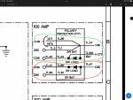
Yea, that is the polarity protection box. It is just a set of diodes that prevents batteries that are connected backwards from doing damage in the cab. To get you off the lot, it can be bypassed, just don’t hook up your batteries backwards.

In the attached pic, connect the wires circled in red together(12v batt, alternator and load to cab) and insulate the connection. Then repeat the process for the wires in the green circle.

B2C8B895-E22D-4C51-BADA-B4E46FD77657.jpeg
 
Top
AdBlock Detected

We get it, advertisements are annoying!

Sure, ad-blocking software does a great job at blocking ads, but it also blocks useful features of our website like our supporting vendors. Their ads help keep Steel Soldiers going. Please consider disabling your ad blockers for the site. Thanks!

I've Disabled AdBlock
No Thanks