• Steel Soldiers now has a few new forums, read more about it at: New Munitions Forums!

  • Microsoft MSN, Live, Hotmail, Outlook email users may not be receiving emails. We are working to resolve this issue. Please add support@steelsoldiers.com to your trusted contacts.


Frequency Transducer compatibility

RWG421

Member
83
0
6
Location
Chandler , AZ
This issue was a side-bar in my (Mep 002A Battery Indicator post 9/26/2011) I hope I am following the sites mores in making it a new post.
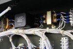
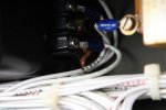
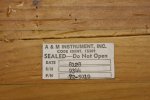
I contacted Delks and they have a “new transducer ” (pulled from a new unissued replacement panel) . Mine is an A&M, and the transducer Delks has on hand are Technology Research Corporation. They stated that it should work with my meter….They think.
Are the Frequency Transducers a “Mil Spec item” like a M16 bolt and interchangeable between manufactures? The cost is $55.00 for the transducer, or $110.00 for transducer & gauge. I hate to waste the money and buy both (That’s almost 10% of my mep’s acquisition cost):shock:
Are they straight shoots at Delks? I would hate to blow up a otherwise fine working genste, or waste time and money.
Thanks all for your advice,
 

Attachments

Last edited:

doghead

4 Star General /Moderator
Staff member
Super Moderator
Steel Soldiers Supporter
26,247
1,168
113
Location
NY
Delks is very reliable.
 

PeterD

New member
622
6
0
Location
Jaffrey, NH
There are at least two versions, not compatible between them. The meter movement is different (different full scale current), so you should ask the seller to confirm what the meter movement full scale current is, and if that matches then it should work OK. Keep in mind that it is likely the different versions were widely separated in years (I think one I have is from the 60s, and the other from the 80s, so about 20 years) however, both look very similar.
 

JimH

Member
33
0
6
Location
Delaware, OH
As an alternative, you could look around for a reed resonant meter, and eliminate the transducer. These were quite popular on the older generators, and quite frankly, IMHO more reliable. I have purchased 3 of them from that online auction house in the past few months.

Jim


Keith_J

Well-known member
3,657
1,313
113
Location
Schertz TX
My frequency meter is corroded to death. I just bought a digital multimeter with frequency measurement capacity and use that. As a bonus, it is true RMS, meaning proper measurement of alternating current.

If your transducer is working, it would be best to keep it. Have you tried to plug the oil leak?
 

RWG421

Member
83
0
6
Location
Chandler , AZ
It's on my list for tomorrow. I'm just concerned that the fluid loss that has already occur will cause the unit to fail when I need it most.

I was hopping to have a cost affective back up.

Is the fluid to disperse heat from the voltage conversion?
 

Isaac-1

Well-known member
1,970
48
48
Location
SW, Louisiana
If you are looking for a cheap way to measure frequency, look at the basic Kill-A-Watt, they do surprisingly well with generators (many lower end multimeters will give crazy false frequency readings due to distorted wave form and noise from generators).

Ike
 

Keith_J

Well-known member
3,657
1,313
113
Location
Schertz TX
It's on my list for tomorrow. I'm just concerned that the fluid loss that has already occur will cause the unit to fail when I need it most.

I was hopping to have a cost affective back up.

Is the fluid to disperse heat from the voltage conversion?
Not as much as it to prevent water intrusion. From the looks of your unit, it has never gone swimming. If you keep it out of the weather, you should be fine.

There isn't any real heat generated in the transducers. Only a few microamperes. I measured between 20 and 554 microamperes for an equivalent of 56 and 65 Hz output. Meaning it is 290 microamperes for 60 Hz. At a bit over 2 volts, it is 0.30 milliwatts of power. Which even if the transducer were 1% efficient, would still be a tiny bit of thermal energy.
 
Last edited:

Keith_J

Well-known member
3,657
1,313
113
Location
Schertz TX
I took my transducer out to look at the potting. Mine is a Technology Research Corporation unit in a spot welded case, sealed with silicone caulk and then potted in silicone rubber. I wouldn't worry a bit about the leaking oil causing failure.

Same part number so they should be interchangeable. I took it out to make measurements using utility power for constant 60 Hz. loading it through a variable resistor from 580 to 970 ohms to measure the voltage over the resistor. At 580 ohms, voltage is 44.3 mV. At 777 ohms, voltage is 60 mV. At 974 ohms, voltage is 75.3 mV. What does this mean? Ohm's Law where voltage equals the product of resistance and current means 60 Hz input yields an output of 77.3 microamperes.

So, if you have a sensitive multimeter, a 10-20 turn 1k Ohm variable resistor and time, you too can check your transducer to see if they are indeed interchangeable!

I'm using this to rebuild the frequency meter, using a surplus movement with the original frequency meter's scale and case. Why? Because I like the challenge.
 

JimH

Member
33
0
6
Location
Delaware, OH
Wow!

All the meters I have seen on 002's and 003's (admittedly just a dozen or so) have all been 200ua full scale meters. The meters have all shown 60Hz to be half scale. That tells me that the transducer is outputting 100ua, when the input is 60Hz. My trusty Simpson 260 (I know I am old school) can then check a transducer without removing it from the control box, but just by removing the wiring to the suspect meter. With another meter to measure frequency output from the utility plug (Hardy Diesel makes a nice one, cheap) I can verify the output by reading 100ua on the Simpson. You have to be careful because there is voltage from the generator running around in the control box. This should tell you whether the meter is bad, or the transducer.

Your results may vary. Caution is necessary when the control box is open and the generator running. You can also do the same thing by removing the meter and transducer, hooking them back together, and using (what we call at work) a suicide cord to hook the transducer to 120VAC.


Regardless of the method used, it should be easy to identify the problem part. Safety first, though. There may be other meters and transducer combinations used, but I have not seen them.

Oh, I am not affiliated with Hardy Diesel, just a satisfied user of one of their products.

Jim
 

Keith_J

Well-known member
3,657
1,313
113
Location
Schertz TX
That troubles me...unless the transducer's output varies based on impedance (resistance) and measuring its output at higher values (400+ ohms) causes output to drop.

Do you have any solid DC resistances on the typical 002/003A frequency meters? I measured 570-580 ohms on two samples, one working and the other rusted to pieces. I thought the rusted one was accurate as I had pulled the hairsprings off the connections (current flows through the springs).

I did note the transducer has adjustments for both spread and balance, both factory sealed with red sealant and undisturbed.
 

JimH

Member
33
0
6
Location
Delaware, OH
If you closely examine both the transducer and the meter, you will find that the output of the transducer is DC, as is the input of the meter. The meter is measuring the amount of current put out by the transducer and translating that into frequency, on the scale of the meter, from 0 to 200uA. Introducing resistance into the circuit will cause the meter to read differently. the meter is not measuring resistance, it is measuring current.

These circuits are not known for great reliability. A digital replacement would be more accurate and probably more robust.
 

Keith_J

Well-known member
3,657
1,313
113
Location
Schertz TX
If you closely examine both the transducer and the meter, you will find that the output of the transducer is DC, as is the input of the meter. The meter is measuring the amount of current put out by the transducer and translating that into frequency, on the scale of the meter, from 0 to 200uA. Introducing resistance into the circuit will cause the meter to read differently. the meter is not measuring resistance, it is measuring current.

These circuits are not known for great reliability. A digital replacement would be more accurate and probably more robust.

True, but the "full scale" needle movement (bump stops) is wider than the 55-65 Hz "window". I deduced the function of the meter by pure observation. Just like a shunt ammeter, the scale is arbitrary. only through the current-frequency instead of Ohm's Law.

The transducer is a current source, meaning it varies voltage to result the current. The moving coil in the meter indeed has a resistance, it is in the 550-600 ohm range since copper (the wire used) has a resistance which varies with temperature. That is why they use current instead of voltage in the transducer. I am using a resistor to mimic that, only most resistors have much lower temperature coefficients.

I'm certain of the frequency of my utility power, with my digital volt meter, it is only 59.9 or 60.0. My next experiment will be using another digital volt meter (instrument) and the 777 ohm shunt, comparing the actual frequency against the voltage drop over the shunt. By doing so, I will have an even more accurate, yet more arbitrary "frequency meter" with only one calibration point, 60 Hz.

Yes,the meters are FRAGILE.
 

JimH

Member
33
0
6
Location
Delaware, OH
You have to be careful, and be sure you are not measuring voltage or current. A transducer is a tuned circuit, which when it comes into resonance (around the frequency of 60Hz), outputs a small current that can be used to indicate the actual frequency of the AC.
If you are just using a resistor, you are measuring voltage or current, but not frequency. In this case, the tuned circuit is tracking the AC frequency output for adjustment purposes of the generator.
 

Keith_J

Well-known member
3,657
1,313
113
Location
Schertz TX
The frequency transducer makes a current that is an analog of the frequency. Back in the 70s when these were designed, high speed digital circuits, timers and counters were far outside of the mature state for a toughened military service.

The meter is nothing more than a micro-ampere meter, using a moving coil in a permanent magnet field. The torque is proportional to the current, this torque is opposed by torsion springs on the needle. There, torque is proportional to needle displacement. This is why the scale is linear.

If the output of the transducer were anything other than pure DC, the needle could vibrate. I have not seen any AC component of the DC output at up to 100 kHz. Nor have I seen any signs of pulse width modulation, indicating adequate output filtering.

My degree in engineering may be mechanical but I've had 10 hours of network theory, linear and analog circuitry. Plus I've worked in the field of motion control and instrumentation.
 

Isaac-1

Well-known member
1,970
48
48
Location
SW, Louisiana
I am having a problem with the frequency meter on my MEP-016b, it reads higher than the actual frequency by about a 1/2 hz (when compared to measurement by my Fluke 87V and Kill-a-watt). Before digging into things too much, my first thought was possible added resistance due to old dirty connections, however it seems if that were the case it would read off in the other direction, can someone double check my logic on this. Also are these meters adjustable, the manual mentions adjusting to a known good reference meter, as well as instructions on limited range calibration adjustment of the transducer, but gives no information on adjusting the meter, I assume it does not really mater much if the fine tuning adjustment is at the meter or the transducer since we are talking less than 1 hz.

Ike
 
Last edited:

PeterD

New member
622
6
0
Location
Jaffrey, NH
Half a Hz?

For the record (such as that is!) the screw on the meter is the 'zero adjust' and would typically be used to set the zero point, and the adjustments on the transducer are the ones to set the frequency (60 Hz for example) dead on. However, my (perhaps limited) experience is that the analog type meters are seldom accurate to better than that half a Hz!
 

Keith_J

Well-known member
3,657
1,313
113
Location
Schertz TX
The meters are sealed. The screw on the crystal slightly alters the spring force keeping the needle to the left (in this case). Changing it for a single point calibration is perfectly fine since 60 Hz is the desired reading. These meters have internal balance weights which are adjusted at time of manufacture which could have shifted, most likely corrosion is why this meter reads incorrectly

Resistance changes from transducer to the meter do not matter, within reason, since the meter measures current and the transducer produces the current irrespective of voltage. Resistances of conductors change with temperature.
 

Isaac-1

Well-known member
1,970
48
48
Location
SW, Louisiana
Given that we are going into winter soon I will see what changes colder weather have before making any adjustment, it was 92 degrees on Saturday when I compared it to the digital meters (I had noticed this in the past, just don't remember how far off the meter was).

Ike
 
Top
AdBlock Detected

We get it, advertisements are annoying!

Sure, ad-blocking software does a great job at blocking ads, but it also blocks useful features of our website like our supporting vendors. Their ads help keep Steel Soldiers going. Please consider disabling your ad blockers for the site. Thanks!

I've Disabled AdBlock
No Thanks