• Steel Soldiers now has a few new forums, read more about it at: New Munitions Forums!

  • Microsoft MSN, Live, Hotmail, Outlook email users may not be receiving emails. We are working to resolve this issue. Please add support@steelsoldiers.com to your trusted contacts.

Fusible link from Alternator and Charging Issues

forest522

Member
308
4
18
Location
Bernalillo, New Mexico
Ok, I'll be to the point. Like many here, I put a lot of time and research into this obsession.

Just when you think it is all ready...

I am only getting 12.4 volts at the batteries while engine running. Removed and had the Alternator tested (lifetime warranty from OReilly). Watched the test happen at the store - 14.4, green light passed, test. Hmm.

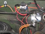
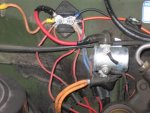
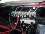
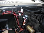
Ok, cleaned and checked all the wires. Replaced a fusible link from the Bat post on the alternator to the Positive Terminal Block as indicated in the TM and wiring diagram (used 8 gauge SXL from Alt BAT terminal and connected to 12 gauge Thermo HW). Longest portion of that wire is the 8 gauge SXL with the last few inches fusible link as seen on the rest of the vehicle).

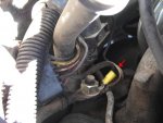
Now, still have 12.4 ish volts at batteries, and the fusible link portion of the new wire is warm to the touch. Just warm, not frying hot. I have been afraid to leave the driveway and take her on a long test drive, not sure if we will return or not!

My question is this...is the warm wire just because it is charging batteries? AOr is there a voltage regulator problem somewhere? What is up with the voltage? Why not 14.4?

This is a relatively new issue, after a month of other issues getting resolved. The 12 volt conversion, I think it was well done and included new starter and alternator, has been retraced by me and follows the Rosscommon method.

Any suggestions or war stories are welcome! Thanks!!!
 

cpf240

Active member
1,479
5
38
Location
Free in Northern Idaho
What is the output of the alternator when measured at the back of the alt? Perhaps the alt is not getting the signal to start charging?

If the output at the back of the alt is 14.4~, then measure at various points along the cable to the battery and see if the point of loss can be determined.
 

forest522

Member
308
4
18
Location
Bernalillo, New Mexico
Will do, I read one of your earlier threads about the Rosscommon conversion not charging.

More info - All new bulbs and cleaned instrument cluster. Dielectric grease, shiny brass on the connections. A 194 bulb is on Gen 2. It lights up with a turn of the key, WAIT light on, then off, she starts right up. Still just 12. 3, 12.4 at battery terminals.

Also, to test at the exciter, do I just stick the positive end of the multimeter in the brown line then the black to a ground?

Thanks!!
 

Keith_J

Well-known member
3,657
1,315
113
Location
Schertz TX
The alternator MAY be hooked up incorrectly. Double check the sense wire, it too may be bad.

I have assumed this is for the right side alternator, the one charging the back battery. The 8 AWG wire going to the back battery is solid red, the 8 AWG wire going to the front battery (isolated ground) is red with a white stripe and goes to the positive term on the FRONT battery, which is also the negative term of the back battery.

Ok, confused?
 

forest522

Member
308
4
18
Location
Bernalillo, New Mexico
Yes, but that is normal. The sense wire is the brown correct? And a reminder, this is a 12 volt conversion vehicle. Runs and sounds good, Rosscommon followed and double checked. aua
 

forest522

Member
308
4
18
Location
Bernalillo, New Mexico
You may be right sir, it is dark and rainy here, but a quick test found that with headlights on, the voltage at the batteries was 12...11.9

I will check again in the morning to verify. Both batteries are not very old, just a year.

If just one cell is bad would that bring the whole system done?
 

M1008driver

New member
522
3
0
Location
Great Falls, Montana
I read the Roscommon 12 volt conversion. Is that red wire on the passenger side alternator isolated ground replaced with a ground?

Add a ground wire from the ground terminal
of the passenger’s side alternator to the
engine. The wire removed in Step 12 can
be used.
The other area I would look real hard at is the 12 volt junction block. It is easy to mistake one wire for another.

9. The two alternators are connected together
at the 12-volt junction block. The two red 8
gauge wires come together into one ring
terminal on the larger stud of the 12-volt
junction block. (On the unit done by REC
these wires had blue fusible links on the
end.) Disconnect these wires from the 12-
volt junction block (Photo 3).

10. On the smaller stud of the 12-volt junction
block a red 14 gauge Wire is attached. (On
the unit done by REC, this wire had a
brownish-orange fusible link on the end.)
Disconnect this wire from the 12-volt
junction block (Photo 3).

11. Insulate the ends of the wires removed in
the two previous steps, bend the wires back,
and secure them to the harness.
Other than that I have no other ideas to help you. I would print the 12 volt conversion instructions and retrace everything.

http://www.roscommonequipmentcenter.com/news_notes/nn10.pdf
 

M1008driver

New member
522
3
0
Location
Great Falls, Montana
The 12 volt Roscommon conversion is not that hard. I had to really look at the 12 volt bus bar to make sure I disconnected the right wire. I have no idea what would happen if I was wrong as in whether the alt would work or charge properly. The other thing that surprised me was the PS alt needing grounded after removing the red wire.

I do think your problem is related to the alt and it's wiring since you had it tested. Let us know when you get it fixed.
 

forest522

Member
308
4
18
Location
Bernalillo, New Mexico
Ok, so far I have checked and recheck the wiring from the Passenger side Alternator and beyond. I have even labeled the wires with my wifes handy label maker. Several wires have been be replaced with all new connections and some the whole wire is new as specified in the schematics.

Still, there is more voltage on the batteries when the vehicle is off than when running.

12.3 running, 12.5 -.6 when off. Amazing.

I removed the positive terminal bar and shined it up. All the connector rings from wires are shiny and/or new.

Tomorrow I will have both batteries tested, but I don't see how they could be the issue.

The horn is and has been disfunctional since I bought it. The fused removed and the issue saved till later. Is there any way the horn could be part of some wierd circuit issue here?

Any other ideas gents? I am trying not to get too frustrated here. Good thing I dont have a gigantic catapult, or ...well you know...
 

cpf240

Active member
1,479
5
38
Location
Free in Northern Idaho
I didn't see it posted, but perhaps I missed it... what are the alternators putting out measured at the back of the alt?

For the horn problem, what is the problem? If the horn is sounding continuously, check for a bad diode on the horn relay. You can either replace the diode, or just remove it. If the diode fails in a shorted condition, the horn will stay on.
 

Warthog

Moderator
Super Moderator
Steel Soldiers Supporter
13,775
227
63
Location
OKC, OK
I have been following this thread, just haven't had time to post.

Let's run a few tests.

Remove the 2-pin plug from the alternator and check the voltage. You should have these readings.

Key off
red plug - 12v
brown plug - 0v

Key on
red plug - 12v
brown plug -12v

The Rosscommon method for 12v conversion still uses the GEN2 fuse, relay and diode. Just changes fron 24v to 12v.

We only have a few things that will affect the circuit.

Excitor plug
Positive lead
and ground (you did replace the alternator with a civvy unit didn't you?)

If needed we can wire the alternator as a stand alone system for testing purposes.

Make a jumper wire for the positive output and a test jumper for the exciter. Buy a replacement plug from the parts store (under $5), twist the two wires together and add a jumper. Plug it into the alternator and attach to the battery.

Start the truck and check you voltages at the barrey and the back of the alternator.

exciter Jumper.JPG
 
Last edited:

Skinny

Well-known member
2,130
486
83
Location
Portsmouth, NH
Sounds like a shorted battery is dragging the charging voltage down which is probably causing that fusible link to get very hot.

What is the open circuit voltage of the battery with the engine off? If it's 12.4, then it sounds like nothing is reaching the battery. That doesn't explain why the fusible link would be hot.
 

forest522

Member
308
4
18
Location
Bernalillo, New Mexico
Warthog - yes the alternator is a civy unit. The Ultima from OReilly's, the one that would go into the 1975 cadillac, heavy duty and isolated. It is grounded as indicated in the Rosscommon directions. I still have the original passenger side alternator. It was missing the drivers side one when I bought it.

This truck came to me with only one alternator, hacked wiring and a dying starter. Thus the conversion was begun...probably should have just rebuilt the starter, bought another alternator and re-worked the wiring...heck I would be nearly done with that at this rate!

I was unable to make it to battery store to test batteries, but this is what I have done so far.

Last night, charged both batteries overnight - each was 13.3 this morning. While doing some other work on it I started it a few times and idled til warm. System drained down to 12.2 or so. Checked red wire and BAT terminal on alternator - same voltage as batteries...12.2

Heading back out before the rain starts again to do the checks that Warthog recommended. Will be back soon.

THANKS!!!
 

forest522

Member
308
4
18
Location
Bernalillo, New Mexico
Replaced both relays under the dash next to the starter relay - the exciter and the voltage meter. They both had lots of corrosion. Cleaned the connections, di-electric grease and bolted back up.

Still 12.3 volts and dropping...placed charger on for the night. Will revisit in the morning.

cpf240 - as for the Horn issue...long ago when I first picked it up, there was no horn fuse. Replaced fuse and horn stays on. Removed the diode, no change. I had several other issues that were bigger in picture so I moved on. That one is still on the back burner...

So, 13.3 after charging, starts great all lights come on as ought to, runs well, system power at 12.8 or so then starts to drop.

Maybe a bad cell in one of the batteries?
 

M1008driver

New member
522
3
0
Location
Great Falls, Montana
I have successfully done the Roscommon Conversion. It seems like your alternator is not getting excited. Mine starts at about 12 volt and goes up to 14.4 volt after about 10 seconds after starting my truck.

My 12 volt junction before and after. I do have some accessories connected too. Notice the two blue fusible link wires and the kind of orange wire touching them are no longer connected.
 

Attachments

Last edited:

forest522

Member
308
4
18
Location
Bernalillo, New Mexico
Load tested both batteries this morning. They are in good shape, no bad cells. Hmmm.

Back to the drawing board. There is a ground strap from the firewall to a bolt on the top, back of the passenger side engine block. A braided wire deal. It looks like **** and is frayed. I'll replace that and report back.
 

forest522

Member
308
4
18
Location
Bernalillo, New Mexico
Ok, we have success. Good news, the charging system is back up to 14.4 volts. After a third attempt at rooting through wires, cleaning grounds and replacing fusible links I located what I think was the issue. Or at least a combination of electrical snafu's that made the issue.

Attached is a photo of a ground located in on the top, rear of the engine block, passenger side. A braided copper strap that grounded to the firewall. It was pretty bad. I replaced that and thoroughly cleaned the bolt and every other ground I could find. A switch had been installed that grounded the glow plug relay allowing the operator to manually activate the glow plugs. I removed that as well, just a hunch. Both relays under the dash near the starter relay were checked, corroded. So I replaced them as well. Turns out - one or all of the above or a combination created a situation where 2 volts were draining somewhere.

Now removed, she charges the batteries fine. On to the next issue, there are many...but that means I have more time learning how this thing works!

Thanks to all who offered help! The lesson learned here is comparing and tracing the wiring diagrams...labeling wires and cleaning every ground and electrical connection you can find.
 

Attachments

Top