• Steel Soldiers now has a few new forums, read more about it at: New Munitions Forums!

  • Microsoft MSN, Live, Hotmail, Outlook email users may not be receiving emails. We are working to resolve this issue. Please add support@steelsoldiers.com to your trusted contacts.


G204 Rectifier help plese

spocter

New member
20
0
0
Location
ny
Hello all;
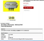
I am new here and if this is the wrong place to ask,please let me know and I apologize. Anyway, I have had this G204 Hobart welder for about ten years or so. It runs and works great. I usually don't use it much but run it at least 2 times a year to keep it lubed up. I asked my son to please put the battery in it the other day and he hooked it backwards (positive ground). When I started it,it blew the rectifier clean (separated from steel mount) off and lo-and-behold, no more charging. I realize the rectifier is now trashed,but was wondering what else might have gone bad. I test the 3 leads (while running)with a test light and the battery lead lights.then tested both coming from front of engine. One lit twice as bright as the battery one and the other doesn't light at all. Does this mean something else was trashed? I know very little about this. I also have been searching the internet for this part YJ68 with very little luck. I thought I read somewhere on here that someone found them for 13 dollars,but don't remember where. I would really appreciate some info on this. Thank you all very much in advance. PS If anyone might have one of these rectifiers, please let me know.
 
Last edited:

Warthog

Moderator
Super Moderator
Steel Soldiers Supporter
13,775
227
63
Location
OKC, OK
Welcome to SS

Moved to the Aux equipment forum.

Speddmon is a great resource on gen sets. He might know the answer.

Being Memorial weekend it may be a while before you get a response.
 
Last edited:

Speddmon

Blind squirrel rehabiltator
Super Moderator
Steel Soldiers Supporter
4,640
28
38
Location
Cambridge, Ohio
First thing is first get a good volt, ohm meter. You can not check the charging system with a test light. It will tell you nothing of any importance.

The two leads coming from the front of the engine, I assume, would be the stator leads. If the engine is running, you should see an AC voltage on those two wires. Since you had your son put "the battery" in it, I am going to assume it is 12 volts????? If it is a 12 volt system, you should probably see somewhere in the neighborhood of 15 to 17 volts AC on the two wires. If it is a 24 volt system, then you should see around 33 volts or so on these two wires. If you get the proper voltage, it would appear that all you might need is the rectifier and possibly the regulator. If it's a 12 volt system, any 12 volt rectifier would do, unless you want to keep it OEM. If it's 24 volts, that rectifier might be a bit harder to find.

Good luck.
 
Last edited:

spocter

New member
20
0
0
Location
ny
Speddmon;

Thank you very much for your reply. I have replaced the rectifier with a Kohler Rectifier/regulator PN:41-403-05. It is a 12v system.This is what is happening. With the stator leads connected to rectifier and engine running, I am getting 19v AC from "B" connection according to the meter. As I am getting older, I find myself second guessing everything I do. I have been messing up alot. Anyway, I had it mounted to the engine,(grounded) and I get 13 volts AC from "B" connection. Shows .6 on DC setting. OK here's the thing. when I try to connect "B" from rectifier to amp meter, it sparks as if it were grounded,engine running or not. I just barely touched it,but both should be positive,or so I thought. When the machine is off I can put a test light to + on battery and it will light touching "B" on rectifier ( as seems to be grounded). I don't want to trash this rectifier too Should it be mounted to engine (grounded)?. I also did all this with original regulator connected and disconnected. If you get a chance, could you please let me know what you think? Thank you very much....Len
 
Last edited:

Speddmon

Blind squirrel rehabiltator
Super Moderator
Steel Soldiers Supporter
4,640
28
38
Location
Cambridge, Ohio
How much of a spark are you getting? Just a little spark like it's charging a small capacitor, or a large spark like you are trying to weld with your battery?

Without having ever seen the rectifier/regulator you are talking about I'm gonna take some guesses here.

The regulator should have three terminals on it. I assume that one of them is marked with a "B" (from your post above), indicating to me that is PROBABLY the battery terminal. That should go to the positive terminal of your battery. The other two terminals are what the stator leads connect to. Since they are an AC signal, it deosn't matter which wire goes on which terminal.

You are correct in the fact that the regulator is grounded by mounting it on the frame somewhere. That is where it get's the negative battery connection from. With the engine running you should be seeing 19 volts AC (give or take) on the two terminals where the stator is connected (one meter lead on one terminal and one on the other). And you should see 14 volts DC or so from the "B" terminal to ground.

All of the connections should be done with the regulator mounted solidly to the frame somewhere, and if you connected the leads up wrong and started the engine you probably fried that regulator as well. If you started the engine without having the battery connected or the regulator grounded, it's possible it's bad as well.

All I can say is mount the regulator and make sure the wires are hooked up properly and check for the voltages where I told you to and see what you have. If they don't match up, the regulator could be bad.
 

spocter

New member
20
0
0
Location
ny
Thank you so much Speddmon for all your help. I know I have been pretty vague on my descriptions and such,but I hope this is better.The Rectifier/Regulator is described as follows : [FONT=Arial, Helvetica, Trebuchet MS]Regulator Rectifier Assy.
12 Volt, Series Type, 14.4 Vset ..
[/FONT][FONT=Arial, Helvetica, Trebuchet MS]For 15 amp permanent magnet charging systems.
Terminal ID: AC, B+, AC. The spark is quite significant. Stator to stator voltage with machine running is 39.5v AC or stator to gnd (1) 19.3v AC..(2) 19.7v AC. With Rectifier/regulator (I am guessing it is a combo unit) mounted, grounded, and connected to stator, B+ to ground reads .01v DC (point zero one). The unit has a master disconnect on it so I shut down power, connected B+ to amp meter and momentarily turned on power. Amp meter shows instant -15v and wire gets warm. Quickly turn power off and goes back to zero. It does same thing whether I have original regulator connected or disconnected.Wire to amp meter is original that I disconnected from original rectifier. I have the wiring diagrams for both the unit and regulator/rectifier assy and all wires are where they are supposed to be. I think that because of this "short scenario" I may have trashed the new rectifier,but for the life of me, I cannot figure out where the short might be. Everything worked great before the battery error.No wires were changed anywhere else.I hope this post is a little better. Please let me know if I missed anything and thank you again so very much for all your help.....Len

PS> Strange thing about the (short scenario) is that there is no short until I try to connect to +B terminal on rectifier. When I turn power on, it shows 12vDC at end of wire that connects to rec.
[/FONT]
 
Last edited:

Speddmon

Blind squirrel rehabiltator
Super Moderator
Steel Soldiers Supporter
4,640
28
38
Location
Cambridge, Ohio
[FONT=Arial, Helvetica, Trebuchet MS]PS> Strange thing about the (short scenario) is that there is no short until I try to connect to +B terminal on rectifier. When I turn power on, it shows 12vDC at end of wire that connects to rec.[/FONT]
That would kind of make sense to me because when you turn the power on your battery is now energizing the circuits of the welder, and the regulator would then be ready to start charging the battery when ever you would start the engine. Since you are geting a short to ground, that regulator is bad.

Did you try to run the engine without the regulator grounded, or with the wires hookes up incorrectly? Also, 39.5 volts from the stator seems like it's awefully high for a 12 volt system to me. Are you sure that the original battery wasn't a single 24 volt battery and therefore it would need a 24 volt charging system?
 

spocter

New member
20
0
0
Location
ny
No, I never did run it with the regulator un-grounded. I have not removed the regulator from the mount. It has a plug that fits together and wires are color coded.
After trying the new Kohler rec/reg and it not working, I did unplug the regulator and tried it. Was still no go. The 39.5v AC , red and black from meter to each stator lead. Individual from stator to gnd were about 19v AC. No, The original battery has always been 12v and is a 12v system. I have had this for a long time and have used it many times. All worked perfect before mishap. Even now, battery doesn't charge, but everything still works as before,welder,gen,etc.. Really don't even need battery to charge because it has a real good battery and could start for a long time w/o charging. I just want to get it back to where it was.I have been using the Kohler Rectifier/regulator to try to get it back going because I could not find the original parts anywhere. I did order another Kohler rec/reg today. Correct me if I am wrong,but my plan this time is to leave all power off,mount and ground new rec,attach both stator wires (AC) and attach +B to wire coming from ammeter then turn power on from master disconnect. Would you say this is the way to go?
Being it is supposed to be a rec/reg, should I disconnect the original regulator all together? According to the manual for this G204,,regulator is grounded,but rectifier was not (original rec & reg) Supposedly the Kohler Rec/reg has to be grounded. Also, there is a red wire going to original regulator that comes from stator with the two stator wires. Is that red wire an "exciter" to the stator?. Do you think I need to incorporate it into the wiring of the Kohler rec/reg combo unit? Thanks so much again...I seem to be like the energizer bunny.....keep going on and on and on....sorry... Thanks..Len
 
Last edited:

Speddmon

Blind squirrel rehabiltator
Super Moderator
Steel Soldiers Supporter
4,640
28
38
Location
Cambridge, Ohio
I was just waiting for you to get the new regulator that you ordered.

Your plan for hooking it up sounds good to me. I have no idea what the red wire might be for without seeing a print of the circuit, or if you could follow the wire and find where it goes for sure. I don't think it would be an exciter, typically things like that are permanent magnet type of systems. Newer Alternators nave an exciter circuit, but older ones like this usually don't need them.

Edit: Yes, remove the old components completely from the circuit.
 

spocter

New member
20
0
0
Location
ny
Glad you wrote back..thought you were mad at me. New part will be here on Thursday. The red wire does go to the stator, then it goes into original regulator on one side and other side of regulator goes to same place that rectifier connects to ammeter/battery. I don't know if I can post the schematic part of the stator to show this or not. I do have it though. Do you want me to try and post it?
 

Speddmon

Blind squirrel rehabiltator
Super Moderator
Steel Soldiers Supporter
4,640
28
38
Location
Cambridge, Ohio
yes, that would help out greatly. Or if you could point me in the direction of a PDF of the manual, or if you have one, upload it here as an attachment
 

spocter

New member
20
0
0
Location
ny
I hope I'm not getting carried away with this,but just trying to give as much info as possible. This is what the Kohler charging system looks like. If any of the .jpg's are too small, just right click on them and "save image" to desktop or somewhere and then you can make them bigger.
 

Attachments

spocter

New member
20
0
0
Location
ny
This one says something about upgrade from 3 wire to 2 that I do not understand. It may be helpful in determining red wire location. If I have uploaded too much,please delete accordingly if taking up too much space. I don't mean for that to happen.
 

Attachments

spocter

New member
20
0
0
Location
ny
Hi Speddmon, I got the new regulator today but am kinda skiddish in doing anything with it. Have you had a chance to look at the .PDF files I posted? If you get a chance,could you let me know what you think on the wiring? Thank you much...Len
 

Speddmon

Blind squirrel rehabiltator
Super Moderator
Steel Soldiers Supporter
4,640
28
38
Location
Cambridge, Ohio
Yes, I got a chance to look at them a bit while I was at work the other night. But unfortunately I have been too busy to do much of anything else lately.

Apparently the old rectifier and regulator were build to handle that high of an AC voltage, and there is also the "red" wire to deal with. The regulator/rectifier you bought is totally different from what the OEM system was.

I'm not telling you what to do here because I don't know if it will work or not, BUT, if it were mine (which it's not) this is what I would do.

You have to realize that they used a center tapped alternator coil with an extra "tap" this being the "Red" wire. They did this because when you are welding, you can get some pretty good voltage spikes through the ground and that could destroy your rectifier and or regulator in the OEM system. The fix to this was the added impedance in the coil windings of the alternator (they acted as a choke on the system in the event of a large spike through the ground).

What I would do to try to fix the charging system and HOPEFULLY keep the same type of surge protection the original engineers intended would be to hook up the new regulator/rectifier using only one leg of the alternator output and the ground. By doing this you will be feeding the new regulator with only 19.5 volts AC +/-. This will be closer to what that particular regulator can handle, because I suspect that the 36 volts that your alternator puts out was just too much for it and that's why it shorted out. But, I think in order to make it work similar to the OEM set-up you'll need one specific leg, you'll want the one that is tapped between the "Red" wire and the ground.

To find that lead, use your ohm meter and measure the resistance from each of the AC output leads of the alternator to the "Red" wire. The wire with the least resistance to the "Red" wire would be the wire I would use. That will leave you another unused coil and the remaining part of the coil going to the "Red" wire to help fend off any surges in the system...HOPEFULLY.

So, when you find the proper AC output lead, you would want to hook that lead to the new regulator/rectifier on one of the AC terminals, and connect the other AC terminal to ground. This way you'll be feeding the new part with less than 20 volts. Then hook up the center B+ terminal to the ammeter like the original charging wire was. The other AC output wire and the "Red" wire, you'll want to tape them up good so they cannot touch anything or each other, because the are still generating voltage and can shock you.

I don't have a clue if this will work for you or not, it's just my best guess as to how to make the new part work on your old system. I make no claims that it will not fry your new regulator/rectifier. And I don't know if it will continue to work after you try welding with it. However, if you do decide to hook it up like that, please let me know if the charging system works and whether welding with it has any affect on the charging circuit.
 

spocter

New member
20
0
0
Location
ny
Thank you very much for your reply. I understand everything you are saying. If it works , great,if it doesn't, it doesn't but we gave it our best. Thats all that can be expected. I would just like to clarify one item. Connect unused "AC" from rec. to ground. Would this not short out rectifier. I just want to verify is all. I realize this is an experiment. ALSO, with ohm meter set to 200 scale. I get 2.5 ohms on one stator lead and 2.8 on the other. I am not sure on this if more is less etc. Would I use the 2.5 lead or the 2.8 ohm lead. I know this probably sounds stupid, but I am just not sure on it. Thank you so much for all your help.
 
Last edited:

Speddmon

Blind squirrel rehabiltator
Super Moderator
Steel Soldiers Supporter
4,640
28
38
Location
Cambridge, Ohio
No, it shouldn't..I hope LOL

With the way your alternator is wired, the center tap of the alternator is ground. Think of it in terms of your house wiring. Phase to Phase voltage in your house is 240 volts. Phase to Phase voltage of your alternator is 39 volts. Phase to "Neutral" in your house, which for all intents and purposes is ground, is 120 volts. Phase to ground on your alternator is 19.5 volts +/-. By using the ground on the AC side you are just completing the path for the AC

So when you find the wire I suggested using, you will hook up your new regulator with the B+ terminal going to the ammeter, and one AC terminal going to ground, and the other AC terminal going to the wire I suggested using.

...


The Ohms check you are doing, is checking the leads to the "RED" wire, NOT to ground. Connect your meter like this...

One METER lead touching the "RED" wire coming from the alternator
The other METER lead touching one of the AC wires coming from the Alternator

Repeat the test with the first METER lead still touching the "RED" wire, but move the other METER lead to the other AC wire

Is the 200 Ohm scale the lowest scale you have for Ohms? And yes, the close to 0 the lower the resistance, so the lower one would be the one I suggest using.
 
Last edited:
Top
AdBlock Detected

We get it, advertisements are annoying!

Sure, ad-blocking software does a great job at blocking ads, but it also blocks useful features of our website like our supporting vendors. Their ads help keep Steel Soldiers going. Please consider disabling your ad blockers for the site. Thanks!

I've Disabled AdBlock
No Thanks