

Nate475
New member
- 39
- 0
- 0
- Location
- Glen Burnie Maryland
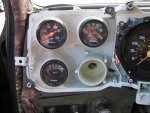
After a lot of tender loving care and time consuming fabrication my gauge cluster conversion is almost finished. I removed the Gen 1 light when I did the 12 volt conversion last year. And as it turns out 2-1/16" aftermarket gauges will fit into this gauge housing with some serious but easy modifications so I decided to go that route instead of replacing everything with aftermarket gauges and a new bezel.
I took a dremel tool with a fiber reinforced cut off wheel and cut out the 3 indicator light tubes. Once I got the inside of the gauge housing sanded smooth I cut 3 pieces of 2 inch schedule 40 PVC pipe and shaped it to fit using a small dremel stone grinding tool. I also had to cut some crude holes in the back of the housing because the gauges needed more clearance. In the end the holes in the back were the same size as the ID of the PVC tubes. I also trimmed the rear mounting studs on the back of the gauges for more clearance. If you are working with high dollar Autometer gauges I would leave the rear posts alone so you can change things later if needed. I chose the cheaper Sunpro gauges so cutting on them did keep the threaded posted tucked inside the housing and away from the printed circuit board and I can always chuck them if I go with a custom dash later. I covered the printed circuit board on the side where I installed the gauges with electrical tape to insulate it and support it now that it's freely hanging off of the back of the housing.
Once I had the pvc tubes perfectly fitted I used a light layer of JB Quick to glue them in place. Then I used JB Plastic Weld which is a taffy roll epoxy with the resin in the middle and hardener on the outside. It has a 25 minute work time and you work it with your fingers. I used 3 tubes on this project with enough left over to fix the broken tab on the left of the housing. With JB Plastic Weld I think I can keep this gauge cluster going for a long time. You can shape mounting tabs with your fingers and add steel to reinforce it. I used it to repair the turn signal hole. The little plastic groove broke apart so I put a dab of JB on it and shaped it with a dremel tool back into something functional again.
I also replaced the dash bulbs with green leds to match the camoclad interior. I should have it back together in a little over a week because I'm waiting on a couple of parts. When I do I'll post the completed pictures of the camo dash and the green lights. I'm also putting a green led light in the 4x4 shifter console. There's a small wedge bulb socket hole present and I found the correct socket to get and led bulb for it. I'll post it in another thread once my parts arrive.
In closing, for those of you intimidated by the wiring, don't be. I wired mine to handle 8 additional gauges and the 4x4 shifter indictor light. All I did was cut the wires going to the voltmeter and I installed 18 gauge insulated wired connectors on them . I then soldered up "T" splice wire harnesses (what I call them) with connectors to create two wires for each of the 4 that were originally going to the voltmeter to create a wire path going in two different directions. A wire path to power the gauge light bulbs and a path to power the gauges. Then I built 4 wire harnesses to handle the job. I learned how to build those by watching youtube videos. You basically turn one wire into several using solder and shrink tubing. And when you get finished you should cover everything up in wire loom tubing to keep the installation clean and to protect the wires. I'll post more pictures once I get my dash back together.
Thanks for all the advice guys and gals,
Nate
P.S. Happy Independence Day!
Attachments
-
 60.2 KB Views: 93
Last edited: