• Steel Soldiers now has a few new forums, read more about it at: New Munitions Forums!

  • Microsoft MSN, Live, Hotmail, Outlook email users may not be receiving emails. We are working to resolve this issue. Please add support@steelsoldiers.com to your trusted contacts.

GEN 2 Troubles

bp m1009

Member
176
0
16
Location
Somerset County NJ/ NE PA
Since I've had the truck my Gen 2 light stays on all the time. I know this means I'm getting no charge to my rear battery and I have had it die on me once. So I'm finally trying to fix it. I have searched and it seems most people are having Gen1 issues or simple things for the Gen2 and cant seem to find much info that helps my situation.

The PO put what appear to be new/newer Alternators on both sides. Gen1 works fine.

Here are some readings I got for Gen2:

Key off: Red Batt wire on top post 12.57v Red wire on lower post 12.47
Top connector red 24.86v brown exciter .004v

Key on: Red batt top post 12.26v red wire lower post 12.47
Top connector red 24.86v brown exciter 25.53v

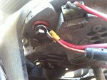
Here are some pics as well. The PO did the wiring.
Alt 1.jpgAlt 2.jpgAlt 3.jpg
 

Durango_USMC

Member
663
0
18
Location
Indianapolis, IN
Check the 28v fuse at the bottom of the fuse block? Gen 2 and Voltemeter relays? Gen 2 light bulb? If you've done all that then I have to say youre stuck in the same spot as me.
 

Durango_USMC

Member
663
0
18
Location
Indianapolis, IN
Cleaned all the contacts? I did and am still stumped unless I fried something. Take a look at the pug on top of the alternator. It looks about as crispy as mine, my next step is replacing that.
 

Warthog

Moderator
Super Moderator
Steel Soldiers Supporter
13,775
227
63
Location
OKC, OK
You have an issue with the engine compartment wiring. The voltage on the top red wire should be 24v not 12v.

First off check the voltage at the 24v Positive Terminal Buss behind the rear battery. You can use the top buss for positive and the bottom buss for the ground. If the voltage is 24v then we will move to the next step. If you get 12v your batteries are wired incorrectly.


Step2. Disconnect your batteries and remove the top red wire. Reconnect the batteries and check the voltageon the red wire. It should be 24v.


Report your findings.
 

bp m1009

Member
176
0
16
Location
Somerset County NJ/ NE PA
You have an issue with the engine compartment wiring. The voltage on the top red wire should be 24v not 12v.

First off check the voltage at the 24v Positive Terminal Buss behind the rear battery. You can use the top buss for positive and the bottom buss for the ground. If the voltage is 24v then we will move to the next step. If you get 12v your batteries are wired incorrectly.


Step2. Disconnect your batteries and remove the top red wire. Reconnect the batteries and check the voltageon the red wire. It should be 24v.


Report your findings.
I did check voltage at the buss on the firewall and I'm pretty sure it had 24v, I will double check tomorrow though.
 

MarcusOReallyus

Well-known member
4,524
811
113
Location
Virginia
I'm getting voltage at the connector so I know its fine.

Not always. If there is corrosion upstream of the test point, and no load on the circuit, a voltmeter may still show the correct voltage. Put a load on it and the reading drops to nothing.

For this reason, I like to verify with a test light. It will load the circuit enough to show the voltage drop. The light will be dim or not light at all.

It's exactly the same principle as the glow plug resistor. If you measure voltage before AND after the GP resistor with the GPs off, you'll see 24v. When the GPs are on, you'll see 24 on the battery side of the resistor, and 12v on the relay side. The resistor drops the voltage only when current is flowing. In other words, only when the circuit is loaded.

Voltmeters draw almost zero current, so you can see a good voltage with a meter, but it goes away when the load is applied. A badly corroded connection or wire is a resistor. Sometimes it can be a very high resistance.
 

bp m1009

Member
176
0
16
Location
Somerset County NJ/ NE PA
Not always. If there is corrosion upstream of the test point, and no load on the circuit, a voltmeter may still show the correct voltage. Put a load on it and the reading drops to nothing.

For this reason, I like to verify with a test light. It will load the circuit enough to show the voltage drop. The light will be dim or not light at all.

It's exactly the same principle as the glow plug resistor. If you measure voltage before AND after the GP resistor with the GPs off, you'll see 24v. When the GPs are on, you'll see 24 on the battery side of the resistor, and 12v on the relay side. The resistor drops the voltage only when current is flowing. In other words, only when the circuit is loaded.

Voltmeters draw almost zero current, so you can see a good voltage with a meter, but it goes away when the load is applied. A badly corroded connection or wire is a resistor. Sometimes it can be a very high resistance.
Thats interesting ​I never thought about that.
 
Last edited:
Top