• Steel Soldiers now has a few new forums, read more about it at: New Munitions Forums!

  • Microsoft MSN, Live, Hotmail, Outlook email users may not be receiving emails. We are working to resolve this issue. Please add support@steelsoldiers.com to your trusted contacts.


Generator works but does not charge my batteries

vinhvinny

Member
43
2
8
Location
atlanta GA
hello all, please help.

I am trying to fix my friend's HUMVEE in exchange for drive time and to learn how to fix humvee's(...while I am still saving money for my own.)

The battery is not being charged when engine is running.

The generator appears to be working: when the engine is running, I disconnect negative battery terminal engine still runs and all lights still turn on. If generator does not work, light should not work, right?

Here is the measurement to determine that it is not charging the battery:

12524114_986404471426071_8295914241337846660_n.jpg

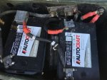
Inside the battery compartment, I don't see any cable coming in to charge the battery, the two red cables as : one goes to the battery, the other one goes to slave :
12718245_986401821426336_2964088592076813371_n.jpg

On the other side of that positive, looking up from underneath the vehicle: that red cable goes to starter motor, below:

12705627_986401868092998_1898473087716830541_n.jpg

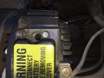
The only cable I see that come from outside is this one, with my finger on it,

Is this the wire where charging power coming in?

1497044_986401894759662_6484487856474041251_n.jpgWhen the engine is running, at this connection, picture above, voltage stays the same but, I think, my 28V generator should increase the voltage if this is indeed the charging cable.

Please help me figure out if this HUMVEE is missing charging cable? Or the above cable is in fact a charging one but it is disconnected somewhere?


THANK YOU VERY MUCH,

VINNY


gcbennet

Member
221
6
18
Location
Trenton, ON
In the battery compt there should be a large POS cable going from the fwd stud that passes through the bulkhead going to the POS stud on the fwd battery. The big NEG cable comes from the shunt to the NEG stud on the aft battery. There's a cable connecting the two batteries together on the other two studs. Make sure this cable is about the same gauge as the other cables, otherwise it will overheat. The generator should be charging at between 27.5 to 28.5 which can be adjusted using a Phillips screw driver on the adjustment stud on top. It's covered by a hex plug Inbd of the cable connection point.
 

Retiredwarhorses

Well-known member
Steel Soldiers Supporter
4,268
3,893
113
Location
Brentwood, Calif
How do you know the generator is putting out the required voltage? Did you meter it at the gen to see if you have 27.5 volts or so? If so, and not at the battery's, it most likely your EESS box is bad. Had one in the shop that did that.
You pic shows 2 POS cables on the power stud, that correct, one is the front battery POS, the other goes to slave cable.
on the opposite side of the positive stud is POS starter cable, you also have a ground from the NEG shunt bolt.
The charging comes through the eng wire harness...routes down the front right of the motor and is on a P-clamp on a sheet metal bracket attached to the oil pan...that harness also has the wire that terminates to the start solenoid.
 

Retiredwarhorses

Well-known member
Steel Soldiers Supporter
4,268
3,893
113
Location
Brentwood, Calif
In your last pic, you should have a larger cable on that bracket...8 gauge , that's where is where charging comes from.
cant really tell from the pic, your finger is in the way...
but if you have only battery voltage at the gen....the gen is bad, most Linley the regulator.
 
Last edited:

vinhvinny

Member
43
2
8
Location
atlanta GA
further testing and investigation

Here is is a better picture of the cable going into the starter. Again, with my observation: this is the only cable from somewhere else that can charge the battery if that is the case, one with my finger on it:

12794554_986884504711401_5316611642384680631_n.jpg

I will open up the alternator and test the actual voltage.


Thank you so much for all your help.

vinny


Attachments

Last edited:

vinhvinny

Member
43
2
8
Location
atlanta GA
Please note I have Prescolite 60AMP gen.

I adjusted the voltage screw and opened up the cover. I got voltage set at 28.5V--within recommended range.

Point A, below:

12806043_987389837994201_6493769901641648975_n (1).jpg

However, at point B, below, the voltage is so crazy, it changes all the time from 3v to 14, to 21 up 24V! Most of the time it fluctuate around 14V:

12799191_987389854660866_8343535172349837237_n.jpg


At point B wire has number 81A, at plug into control box where wire 81A is marked, I check voltage of the pin from battery, it reflects correct 24.5V of battery, I presume the wire is good.r

Is this wire 81A the wire that recharges the battery?

The Control, remote switch box is spotless, spanking new when the HUMVEE arrived. Even the cover cap was still discarded on the driver's side floor. It is very possible that the vehicle has not been used much since this box was replaced--otherwise someone has cleaned up and threw the cap away. . It looks just that new, too.


Could it possibly goes bad being brand new?


Thank you,

vinny
 
Last edited:

gcbennet

Member
221
6
18
Location
Trenton, ON
The best thing to do is pull apart all of the connections and grounds, and clean & inspect them thoroughly. Look for corrosion, damaged, clipped, and repaired wires and connectors. Take nothing for granted and assume nothing on these vehicles. Refer to the diagrams in TM 9-2320-280-20-2 Unit Maintenance Vol 2, under Electrical System Maintenance, Chapter 4, which shows every system you're referring to in detail with the the proper wire placements. Each wire and cable has a metal band on it with a very specific number and the TM shows exactly where they go. Once your truck is put back together as per the TM and you continue to have issues, Unit Maintenance Vol 1 troubleshooting guides, coupled with the vast experience of other forum members will get you through pretty much anything.
 

Retiredwarhorses

Well-known member
Steel Soldiers Supporter
4,268
3,893
113
Location
Brentwood, Calif
As I said in my first post...do you have 27.5 volts or so at the generator, just meter across the ground and the red 8gauge wire...if you have no output from the gen, you will just read battery voltage..24v, or less if you your batteries are weak.
your gen is most likely bad...I also said your charging comes into the battery's via the 8ha wire in your pic..thats the wire laid on top of the POS stud on the starter...it then passes to the POS stud and then to the battery.
that small wire is ste/ice power....not used for your troubleshooting.
 

vinhvinny

Member
43
2
8
Location
atlanta GA
Yes, I have 28.5 at Gen coming from the gen (engine running and Pos terminal of battery disconnected) that is between red cable point A below and a good ground,

12806043_987389837994201_6493769901641648975_n (1).jpg

Please allow to make sure that I understand you:

As the picture be low, the smaller wire coming from the top of the picture is wire 81A, which comes from the connector at the control box below the steering wheel.

do you mean this smaller wire 81A is the charging cable?

And the bottom fat, red wire is the one going to the battery stud:


and below is just the other end of the above bottom red wire on starter.

http://www.steelsoldiers.com/attachment.php?attachmentid=610603&d=1456613089
I also want to note one more time is that when the engine IS RUNNING, battery POS stud is disconnect, the voltage here is very low, ranging from 3 to 23 V, but most hover at 14V...

Do you have a remedy?

My Control Remote switch box (one piece design formerly known as "PCB" box) is spanking new.

thanks
 

vinhvinny

Member
43
2
8
Location
atlanta GA
Yes, I have 28.5V at gen with pos disconnected at batt while engine is running.

It is confirmed that my Gen works, which can powers all light, heater when batt is disconnected.

but that 81A wire in the picture carries very low voltage average 14V, sometimes 3 4 or 23v max.

thanks
 

Retiredwarhorses

Well-known member
Steel Soldiers Supporter
4,268
3,893
113
Location
Brentwood, Calif
81a runs through the EESS...it's probably fried in the box from jump starting...seen it before.
remove the control box, open it up...you will see if it's burnt. Been there, seen That. The other is possibly a bad connection in the cannon plug or burnt shorted wire in the engine harness. I open the box, if ok, I replace the engine harness...then the box.
 

daytonatrbo

Member
320
3
18
Location
Tricities, TN
The fat cable at point "b" in your photos seems to show signs of over-heating, which is a sign of a bad connection.

As everyone else has stated, remove, clean, inspect, and re-connect all major points of connection for both positive and ground.

Start at the batteries, work your way to the starter, and finally to the alternator.


The battery is tied to the alternator via that connection at the starter. The 3 components (battery bank, starter, alt) are "daisy chained" together.

There is no "wire that charges the battery". The power from the alternator feeds into the system as a whole at the lug on the starter. It finds its way back to the battery through the same wire that delivers current to the starter when cranking.
 

tennmogger

Well-known member
Steel Soldiers Supporter
1,576
529
113
Location
Greenback, TN
My 2c. Disconnecting the battery with the engine and alternator running is a bad idea. That simple act can fry the regulator, especially a solid state one, burn out bulbs, and anything else sensitive to Jhigh voltage or spikes. The battery is a huge capacitor to stabilize the peakiness. The regulator will try to bring low/zero volts up by manipulating field excitation. Just because there's some voltage on the system with the alternator turning does not mean the alternator and regulator are working right. The excitation might be maxed out to get NN.N volts out of the alternator.

The only valid in-vehicle test of an alternator is with the batteries connected. Current has to be flowing, and not just the variable load of light bulbs. Measure the voltage of the battery NOT running, which you did, and see 24v. Now measure the voltage across the battery with the engine running and see 28.5 or so, more or less, and that proves the alternator is charging. If there is still 24v (battery voltage) then the alternator/regulator is not working. With no battery the measurement is meaningless.
 

vinhvinny

Member
43
2
8
Location
atlanta GA
I have inspected all connector and box, all seems to be Ok with no burnt marks. But this what I have found:

Sticking the test probe into the 81A wire at the cannon plug, I have either correct 27.3V or 1.6V. One time it is correct another time it is not. There is not telling of when or why the voltage is up and down like that. It must be something internal. And that voltage is the same at battery and at cannon plug in either case, which tells me that the wiring harness actually not broken.

I have an idea, but I need your opinion to see if it is OK to do. Can I run a wire with correct gauge directly from the bolt at alternator, that generates ~28V, to the battery terminal to charge the battery?

Which also means that the alternator is constantly fed with a battery voltage of about 24V at all time, but when engine runs, it in turn charges the battery.

Please let me know if this is OK.

That is point A in picture below:

12806043_987389837994201_6493769901641648975_n (1).jpg
Yes i did clean w contact cleaner spray and sand paper them, too
thank you so much

vinny
 
Last edited:

gcbennet

Member
221
6
18
Location
Trenton, ON
I also had an issue with fluctuating voltage readings, in my case at the engine harness cannon plug to the S3 connector. In spite of external appearances, corrosion inside the cannon plug itself was the culprit.
 

daytonatrbo

Member
320
3
18
Location
Tricities, TN
Do you have a good connection and steady voltage on the small wire on the alt? That's the "exciter wire". It turns the alt "on" when you turn the main switch on in the truck.

There is no harm in running a dedicated wire from the big lug on the alt to the battery, but it seems unlikely to fix your issue.
 

vinhvinny

Member
43
2
8
Location
atlanta GA
I traced all paths, all working, I think the EESS box is bad as far as not putting out good voltage. Otherwise, it still works good and starts my truck. I don't want to fork out $500 changing it while it is still spanking new.

That is why I ask you all for your opinion on my idea of a jumper wire directly to the battery from the generator.

That is my last, cheapest resort. For now.

Thank you
 

vinhvinny

Member
43
2
8
Location
atlanta GA
There is no harm in running a dedicated wire from the big lug on the alt to the battery, but it seems unlikely to fix your issue.
My only issue is the wire 81a does not have good volage (1.3V only) to POS lug on starter to charge my battery. but I don't want to replace the SSI EESS box, which maybe bad--as far as giving correct voltage to wire 81A to charge the battery.

So I might just as well run a wire straight from the big lug on gen to the battery to charge it. If that is Ok, I am a as happy as a little school boy.

vinny
 
Last edited:

gcbennet

Member
221
6
18
Location
Trenton, ON
I'm on my 3rd S3 box in as many years. They just suddenly die for no apparent reason, even when you've covered all of the bases to prevent it. Unfortunately they're a common fail item that isn't cheap to replace because Uncle Sam has deep pockets. The only way around forking out the big coin is to find a local electronics SME who can diagnose and fix the boxes.
 
Top
AdBlock Detected

We get it, advertisements are annoying!

Sure, ad-blocking software does a great job at blocking ads, but it also blocks useful features of our website like our supporting vendors. Their ads help keep Steel Soldiers going. Please consider disabling your ad blockers for the site. Thanks!

I've Disabled AdBlock
No Thanks