• Steel Soldiers now has a few new forums, read more about it at: New Munitions Forums!

  • Microsoft MSN, Live, Hotmail, Outlook email users may not be receiving emails. We are working to resolve this issue. Please add support@steelsoldiers.com to your trusted contacts.

Getting an MEP803a Up and Running

tscott8201

New member
33
0
0
Location
Keystone Heights, Fl.
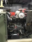
Won an auction on an MEP803a and brought it home 2 weeks ago. The kids had the weekend off baseball so I finally got a chance to pull it into the shop and give it a good solid inspection. I found the diesel tank 3/4 full of nice clean diesel fuel, a brand new air cleaner, Perfect oil in the crank case and what appears to be a brand new oil filter and fuel filter which is all good.
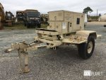
Gen Pic.jpg

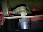
Now for the bad, I found a number of sensor wires and alternator wires cut clean in an attempt, I assume, to render it inoperable before sending it to the surplus yard. I also found the turn in paper work for the final service which notes a "class 3 fuel leak at the injectors". I also found the stop solenoid link bar is missing so the only way to stop the unit is to turn the stop lever by hand and the unit had no batteries. A shot of the missing stop solenoid linkage is below.
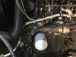
IMG_2889.jpg

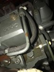
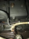
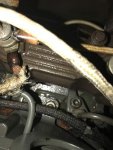
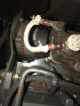
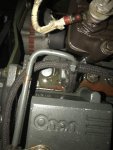
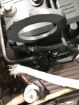
After refilling the radiator putting a new pair of batteries in it and double checking all the fluids and filters I decided to give it a try. The little diesel fired right up and idles effortlessly. After letting it warm up a bit I adjusted the idle to bring it up to 60Hz and that's when the fuel leak showed back up. I had hoped the paperwork I found was the documentation of the repair but alas, I do indeed have a fuel leak somewhere on top of the engine. My prime suspect is the black braided return line on top of the engine but before I could pull lid off the box, it was getting late and I had to call it a night. I used my phone to take a few shots of the top of the engine to see if I could spot the failure but it's not an obvious problem from the photos.
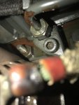
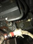
IMG_2902.jpgIMG_2901.jpgIMG_2899.jpgIMG_2897.jpgIMG_2894.jpgIMG_2891.jpgIMG_2890.jpg

So the plan for the tonight is to get the lid off the box, fire up the generator again, and track down that fuel leak. I found the post on here documenting which aftermarket hose is a direct replacement for the existing return line, so I'm good if that's the problem. I also need to track down the parts for the link bar that is missing. The solenoid works but without the link bar to stop it, it just shoots the plunger out when it's disengaged. Where do you all generally get your parts for these units? Ebay? What else might be the cause of my fuel leak? Any information would be greatly appreciated.

Tom
 

Haoleb

Member
197
7
18
Location
Raymond, Maine
Those glow plug wires look seriously overheated at the connections... that is a little scary. I wonder if they got stuck on at some point.

The fuel leak up top there probably is that return hose since most of us have had leaks there. If that is the case you might also be able to detect it by just turning the system to run without starting the engine and since the fuel pump is running and circulating fuel through there you might find some leakage.

I have had good luck getting parts for my unit on ebay or off of other members here.
 

2hot6ft2

New member
16
1
3
Location
Grant, AL
Nice find tscott8201. I don't see anything about what year model that is but I flushed my 2003 with vinegar and distilled water before filling it with antifreeze and distilled water. You would be shocked at the amount of brown crud that came out. You may want to try it once you get the fuel leak under control.

Add a gallon of white vinegar after draining the radiator and run it until the unit reaches operating temp. so the thermostat opens and it get into the motor and mixed good, then let it sit for a day then drain it and fill with distilled water. Repeat the run, set, flush until it runs clear then drain and add antifreeze then run it to let it mix itself good. I'm not sure how much to add to a 803 but the 802 only took 1 gallon for a 50/50 mix approximately. Fill the overflow to the full cold level with antifreeze and it's good to go.

I'll fix that link for you JRM. http://www.lister-petter.com/documents/product/en-LPG[027-09104]1.pdf
 

tscott8201

New member
33
0
0
Location
Keystone Heights, Fl.
Those glow plug wires look seriously overheated at the connections... that is a little scary. I wonder if they got stuck on at some point.

The fuel leak up top there probably is that return hose since most of us have had leaks there. If that is the case you might also be able to detect it by just turning the system to run without starting the engine and since the fuel pump is running and circulating fuel through there you might find some leakage.

I have had good luck getting parts for my unit on ebay or off of other members here.
Agreed on the glow plug wires. I'll be cleaning those up as well. I went ahead and ordered a roll of the fuel return line just in case I need it. Figured it was all probably due to be replaced either way. I've also put a wanted add in the classified section for the missing fuel control linkage.

A local cummins shop should have parts for these as cummins bought onan who bought the lister LPW engine rights. http://www.lister-petter.com/documents/product/en-LPG[027-09104]1.pdf
But first Try replacing the return lines as stated, there is a buried thread on it- those leak and make a mess of things
I can't even seem to find the fuel control solenoid or any of it's associated parts on the Lister Petter website. I'm assuming the control solenoid was part of the generator assembly and not the engine assembly.

Nice find tscott8201. I don't see anything about what year model that is but I flushed my 2003 with vinegar and distilled water before filling it with antifreeze and distilled water. You would be shocked at the amount of brown crud that came out. You may want to try it once you get the fuel leak under control.

Add a gallon of white vinegar after draining the radiator and run it until the unit reaches operating temp. so the thermostat opens and it get into the motor and mixed good, then let it sit for a day then drain it and fill with distilled water. Repeat the run, set, flush until it runs clear then drain and add antifreeze then run it to let it mix itself good. I'm not sure how much to add to a 803 but the 802 only took 1 gallon for a 50/50 mix approximately. Fill the overflow to the full cold level with antifreeze and it's good to go.

I'll fix that link for you JRM. http://www.lister-petter.com/documents/product/en-LPG[027-09104]1.pdf
It's a 2002 model and I've seen the same thing here. The drain is plugged at the very least so I will need at least get that flowing again.

If I can't find the linkage I need, I could easily make one if I had the dimensions of the linkage. From the pictures I've found, it appears to be a simple piece of flat stock with a hole in one end and a slot in the other. Is anyone out there willing to take some measurements of the linkage on their unit and send me the details?

Tom
 

DieselAddict

Well-known member
Steel Soldiers Supporter
2,486
1,890
113
Location
Efland, NC
I would make a linkage. As you point out its a simple slotted bracket. If someone can measure one for you it will be easy to replicate. I'm 3000 miles from mine or I would be happy to do that for you.
 

Guyfang

Moderator
Staff member
Moderator
15,979
22,373
113
Location
Burgkunstadt, Germany
DieselAddict is correct. Your best bet is to make it. Lister Peter will not have those parts, as they were produced for the military, and no one else has a setup like the 802 and 803's. When the linkages "disappeared" in the army, the only hope was to get a CECOM LAR, (Communication and Electronic Command Logistics Representative) to organize one for us, or the steal it. Very low density item. Later, around 2009 or so, a few "Throttle Linkage sets" were purchased to make up shortages in the field, but it was still hard to get. Try submitting a "Parts Wanted" add here in SS. Might be someone parting out a set. If not, simply make one. There is a procedure here in the manuals section for "Engine Stop Screw Adjustment". Might not hurt to review that, also the TM procedure.

Your overheated glow plug wires are mostly caused by loose connections. When they are loose, and preheat is applied, then the bad connections heat up fast! Easy to fix, and once a year reach up there and see if you can move them. Tighten as needed.

NSN's for the Fuel linkage are:

Actuator link: 2190-01-458-7101
Actuator knob: 5355-01-457-8130
Actuator knob, nut: 5310-01-457-8688
Actuator knob, screw: 5305-01-356-9468
Actuator knob, washer: 5310-01-361-5469
 

tscott8201

New member
33
0
0
Location
Keystone Heights, Fl.
Got the lid off last night, boy they sure were liberal with the fasteners on the body of these units. Would it have killed them to use a captured nut?

IMG_2908.jpg

As suggested, I set the motor to run and let the fuel pump show me where the leak was. As predicted, it was at the last tee in the return line before the long run back to the tank.

IMG_2909.jpg

I had some slack so I tried to cut the line back to a better section as a temporary fix to allow me to continue my trouble shooting but the leak persisted after I reinstalled the hose. It's a strange leak, it start out as a weeping drip and quickly accelerates to a full blown spray. I think the long run back to the fuel tank has become blocked some how and the leak worsens as the pressure builds. I found a section of the hose that feels damaged near where the battery sits so that's most likely my issue. I've got an order of new fuel hose coming via mail so I'll just replace the whole return system and nip this problem in the bud.

Question for you all, those plastic tee connectors seem like something likely to break while replacing the return lines. What does everyone use as spares?

I also started work on a link to connect the fuel valve to the solenoid. I found a piece of scrap aluminum stock in my shop that fits in the clevis of the plunger just right. I've got some initial ideas of hole diameter and length of link based on the movement range of the plunger and lever but I've noted in a few pictures that I can find that one side of the linkage has a slot cut in it, I assume to allow the plunder to move a greater distance than the lever. I'm sure I can get the link to work, but if anyone out there could measure their linkage and post the dimensions, I'd really appreciate it.

Tom
 

DieselAddict

Well-known member
Steel Soldiers Supporter
2,486
1,890
113
Location
Efland, NC
I had some slack so I tried to cut the line back to a better section as a temporary fix to allow me to continue my trouble shooting but the leak persisted after I reinstalled the hose. It's a strange leak, it start out as a weeping drip and quickly accelerates to a full blown spray.
This strongly suggests you have a blockage somewhere downstream of the return line. I would suggest removing the cover over the fuel tank and disconnecting the return line at the tank. Put it in a jar and see if you get flow back through the line.
 

Guyfang

Moderator
Staff member
Moderator
15,979
22,373
113
Location
Burgkunstadt, Germany
Good that you ordered enough hose to do the WHOLE thing. Better to get it done now, and feel safe for the next 10 years, or more.

On the whole. the plastic Tee Connectors seem to be very robust. I never saw a busted one, only found them missing. They were easy to get, its standard off the shelf gear.

Look at the figure TM 9-2815-253-24P, Figure 6. It shows you the linkage. The long hole is there to allow the nut, Item 2, to slide back and forth in the linkage. The nut has a, for lack of a better way to describe it, a "sleeve", built into it. The sleeve is what slides back and forth in the long hole. The screw goes through the knob, through the washer, (which allows the nuted sleeve to travel smoothly through the long hole, and not bind) and then through the linkage before screwing into the engine stop linkage. These parts must be assembled tightly, to not allow much free travel, and lose enough to allow the linkage to move without binding. Sounds harder than what it is.

When the fuel pump is running, you should be able to hear the fuel return splashing in the tank, when you open the tank and hold your ear to the opening. If it's not loud, you may need to take apart the fuel lines piece for piece and check/clean them out.
 

zarathustra

Active member
Steel Soldiers Supporter
235
58
28
Location
glasgow,ky
One can buy the hose on ebay from England. It is an odd metric size. I've found that the old hoses can sometimes not exactly leak, but "weep" whereby the whole hose has fuel apparently coming out. New hose will fix that. I also use those spring clamps on all the connections just to be sure.

It's been a while, but I think it was 7mm hose.....
 
Last edited:

TrailLifeBill

Member
Steel Soldiers Supporter
178
4
18
Location
Brunswick, GA
20161111_101947.jpg20161111_100951.jpg OK, here goes... the arm is 95mm long by 15mm wide by 2mm thick. The channel is 8mm high, and the distance center to center from the solenoid pin to the closest part of the channel is 55mm - to the farthest is 80mm. I'm no machinist, but if that doesn't make sense I can try to sketch it out in Photoshop or something.... Let me know if that helps - or if there's anything missing in translation.
 

tscott8201

New member
33
0
0
Location
Keystone Heights, Fl.
View attachment 653449View attachment 653450 OK, here goes... the arm is 95mm long by 15mm wide by 2mm thick. The channel is 8mm high, and the distance center to center from the solenoid pin to the closest part of the channel is 55mm - to the farthest is 80mm. I'm no machinist, but if that doesn't make sense I can try to sketch it out in Photoshop or something.... Let me know if that helps - or if there's anything missing in translation.
Perfect. Thanks. I'll post pics when done.

Tom


Sent from my iPhone using Tapatalk
 

tscott8201

New member
33
0
0
Location
Keystone Heights, Fl.
Finally got around to wrapping this project up this weekend. There was definitely a blockage of the old return line. It looks like someone let it sit under a battery for a few years in high temps. There was about a 6" section of the hose that was completely flat and started to decompose as old fuel lines do. So as planned, I changed out all the return lines and now no more leak. I also bodged together a fuel stop linkage which I think turned out pretty good for 20 minutes work using only scrap around the shop.

Linkage.jpg

After all that, the only issue I had was a minor electrical problem associated with the NO and NC contacts on the oil pressure switch. It was wired so that when the engine had good oil pressure the switch would open and kill the motor. Easy fix there and now she purrs like a kitten. Easy startup every time and not a hint of smoke and all the voltages look good under no load. All indications point to a unit that was moved around a lot but was probably never used for any real amount of time. I'd say the hour meter reading of 125 hours is probably correct.

My next step is to get the house wired to accept the generator and do some load testing and see just how much she can handle. My hope is that I can run the whole house including AC as long as we are careful with our load management.

It'll be a while before I get around to wiring up the house but when I do I'll be sure to post everything here for posterity sake.

Thanks everyone for your help with this.

Tom
 

TrailLifeBill

Member
Steel Soldiers Supporter
178
4
18
Location
Brunswick, GA
Tom - looks great! Glad to hear that your gen is up and running. l am still pondering what the best long-term solution is for connecting into my house panel. I think I may go with an outside 60A disconnect wired to a 60A breaker in my panel with an interlock so that it can't be on when the main is on. I'll still have to wire into the disconnect each time, but that's a 15-20 minute job. Will look for your future additions!!
 
Top