ActionStarCBRxx
Member
- 69
- 1
- 6
- Location
- Hurst Texas
I have an 1986 M1008 CUCV. My truck has already been converted to bypass the glow plug controller. I have had an extermly difficult time getting the truck to start now that it is colder and I am blowing the manual switches. I can push the manual switch for 10 seconds, wait 30, hold 10 seconds, wait 30, hold 10 seconds, wait 30 and truck may turn over but will die. Next hold for 5-7 seconds wait 21 seconds, hold 7 seconds, wait 21 seconds, hold 7 seconds and it may start. This last time I blew the switch.
So I replaced all the glow plugs and now I have questions about how the wiring is supposed to be for the bypass. I do not have a glow plug controller at all. So I have to work with what I have.
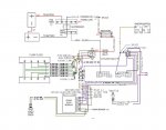
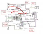
I took the glow plug diagram from the TM and color coded it and I will upload it along with this post.
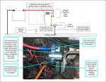
I put a new 50 amp switch in, and a 30 amp fuse. I blow the 30 amp fuse within 1-2 seconds of turning on the switch.
I get the same results when I leave the 24v resistor going to the glow plug relay or if I bypass the resistor and use 12v from the neg of the back battery.
I can take a stab at describing the configuration I have... but it would be easier to draw it out. IF someone who has done this can use my diagram that I am attaching and tell me what to wire the switch too that would be helpful. If possible I would like to be able to have a fuse protecting the plugs from over charging and/or blowing the manual switch.
Attachments
-
61.7 KB Views: 410


