• Steel Soldiers now has a few new forums, read more about it at: New Munitions Forums!

  • Microsoft MSN, Live, Hotmail, Outlook email users may not be receiving emails. We are working to resolve this issue. Please add support@steelsoldiers.com to your trusted contacts.


Glow Plug Relay Rewiring help needed

UncleSam

New member
58
3
0
Location
Anniston Alabama
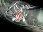
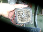
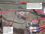
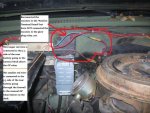
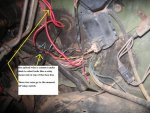
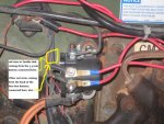
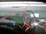
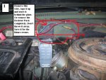
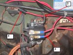
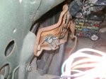
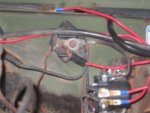
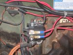
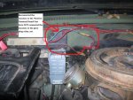
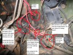
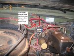
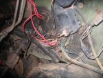
I want to rewire my glow plug relay back to the original setup. But wires have been cut and spliced and I’m not sure where some of them go. There’s one wire coming out through the fire wall with the wiring harness, I need help indentifying, hoping someone can help me and may know what wire goes where. I’ve posted some pictures of what I’ve got going.


:lost:

Thanks for any info.

Uncle Sam
 

Attachments

Warthog

Moderator
Super Moderator
Steel Soldiers Supporter
13,775
227
63
Location
OKC, OK
I may take awhile but we should be able to get Humpty Dumpty back together.

Where are the red wires going to when the pass thru the firewall?

I will post some wiring diagrams in the morning.

The TM diagrams have some errors in the GP wiring.
 

UncleSam

New member
58
3
0
Location
Anniston Alabama
I may take awhile but we should be able to get Humpty Dumpty back together.

Where are the red wires going to when the pass thru the firewall?

I will post some wiring diagrams in the morning.

The TM diagrams have some errors in the GP wiring.
Thanks Warthog,

The red wires that are through the firewall, one is going to the engine wiring harness block on firewall just above the GP relay (always HOT), the other one that is spliced (that someone added jumper wire to, not OE) is connected to the top of the fuse box inside,(also always HOT) I'm not sure where it's going, but both red wires are to the back OE fuse box.

My question is also, should the red wire that is cut and not connected should it be HOT or not? and where should it be connected?

UncleSam

From what I've seen in the diagrams is red wires are from fuse box to "Engine Wiring Harness Block" I may be wrong...:?
 

Warthog

Moderator
Super Moderator
Steel Soldiers Supporter
13,775
227
63
Location
OKC, OK
Questions:

1 - Has the truck been converted to 12v?
2 - How are the batteries hooked up?
3 - Has the starter relay under the dash been renoved?
4 - The cut wire, What part (terminal) of the firewall block is the wire coming out of? Count the colums and rows. Use the example picture as a guide
5 - Is there a manual GP switch on the truck?

More questions to follow.
 

Attachments

Last edited:

Warthog

Moderator
Super Moderator
Steel Soldiers Supporter
13,775
227
63
Location
OKC, OK
More questions:

When I am asking about the firewall block. There are three groups of terminals. Each group serves certain things on the truck. I need to now whick terminal the wire comes out of so I can tell which circuit it is.

6 - In the first picture there are two red wires coming from the battery are. Where are they hooked up at the batteries and on the other end.
7 - In the second picture the 2nd red wire on the firewall block that goes to the 12v terminal block. Which terminal on the firewall block is it coming out of?
8 - Second Pic. The wire that is spliced. Where is it going? terminal number?
 

Warthog

Moderator
Super Moderator
Steel Soldiers Supporter
13,775
227
63
Location
OKC, OK
People always want to change thier trucks to 12v or get rid of the stupid GM wiring.

With a stock system, I can sit across the country and look at a picture or description of a wire and help diagnose a problem.

When a truck has a hack wiring job, your guess is a good as mine.

Sorry for the rant. :rant:
 

UncleSam

New member
58
3
0
Location
Anniston Alabama
1st reply….

1st No, it has not been converted to 12v it’s still 24v.

2nd..Batteries are connected for 24v, voltage reads at positive terminal board 24v

3rd not sure about the starter relay, I’d have to check this evening.

4th The cut wire….in your first picture it’s the same wire that you have a red arrow pointing to.

5th Yes there’s a manual GP switch…of which I’m want to get rid of.


2nd reply…

6th …the wires form the battery…one is going to the Engine Wiring Harness Block, located on firewall just above the GP relay, the other one I think it’s going inside through the firewall and the other end is connected to the (+) side of the battery, but I’ll have to check it out this evening, when I get in to make sure on this one.

7th Not sure… I’ll have to check it out this evening, when I get in.

8th when you ask “what terminal number?” not sure but it’s going to the upper fuse box inside.

I may have to pull the fuse box as per your second picture, to track it down.

Could you check your two red wires that are shown in your first picture and tell me if they’re hot and what voltage with the key switch on or off? This would help a lot.

(More notes in photos) below

Thanks for all your trouble.

Uncle Sam
 

Attachments

UncleSam

New member
58
3
0
Location
Anniston Alabama
I updated the photos with new info should make it easier to see, about where the wires are connected and where there going to.

I didn't get a chance to check about the starter relay. I hope that the new info helps track down the source of the cut wire.

Looking at your first picture again, the wire that you have an arrow pointing to, is the wire that is cut, and not connected in my picture coming from my wiring harness.
 

Attachments

Last edited:

Warthog

Moderator
Super Moderator
Steel Soldiers Supporter
13,775
227
63
Location
OKC, OK
Okay, we will need some pictures of the fusebox. Also pull the manual GP switch out and take a picture of it.

The RED wire that is cut is the 24v feed wire to the bottom fuse. It appears that the PO had an issue with the firewall plug and just bypassed the problem.

I see that you are planning on bypassing the 24v GP resistor pack. Go ahead and diconnect the wire that you previously rehooked up. Dont cut the wire just tape it out of the way. Or you can remove the resistor pack all together.

I all need a picture of how the red wires are connected to the batteries.

How good are you are splicing wires? Do you have a crimpping tool? Ever use shrink tubing?

We will get thru this, just need to do one step at a time. We will be removing the added wiring and fixing what is left. Some of the fusible links will need to be replaced.
 
Last edited:

UncleSam

New member
58
3
0
Location
Anniston Alabama
When you ask if mine was 12 or 24 volt I was thinking starter and the starter is 24v. But after looking at some of doghead attachments of setting up GP relay for 12v, looks like my GP relay is 12v, with a manual GP relay button.

What I'm wanting to do is repair (replace) the GP module so that the "wait" and other dash lights and GP will work correctly with the key switch. And I wasn't sure if those cut and spliced wire had or have anything to do with the GP or GP relay.:?:

Is your GP relay setup 12 or 24 volts? Your Opinion with GP relay 12v or 24v, good or bad?:idea:


Thanks,
UncleSam
 

Warthog

Moderator
Super Moderator
Steel Soldiers Supporter
13,775
227
63
Location
OKC, OK
This weekends assignment:

Disconnect both batteries - negative terminals

Spend some time reading the first few pages of the Troubleshooting section of the TM 9-2320-289-20. It will tell you how to read the wiring diagrams and what the symbles mean, wire sizes, etc.

1. Remove Reistor pack. Either leave it on the firewall and tape up the wires or remove completely

2. Make a jumper wire for the GP Relay. Use #8 gauge Red wire. Approx 8" goes from the 12v Terminal Block to the top post of the GP relay. There is a black one there now. Use red so you will know it is a hot wire. This changes your GPs to 12v.

3. Remove red wires for the manual GP switch. Make a new wire ground wire for the switch. Use black wire and run from the manual switch to the terminal on the GP relay that has the small blue wire. Make another wire from the switch to the ground terminal above the emergeny brake. Most people call this the spider block as it looks like spider legs. You will not put anything back on the terminal with the pink wire. This sets up your manual GP switch.

4. There is a red wire atached to the 12v block. It has a round connector and about 1" of red fusable link. Cut off the round connector and replace the red wire with ~6" of 16 gauge fusable link. The link needs the length to fucntion properly. Put the wire back into the wire loom with the others.

Now comes the fun part.

5. In the center of the firewall terminal block there is a bolt. Remove the bolt and pull the block out. It will take some wiggling and prying buy it will separate.

6. Clean the terminals with Electrical Contact Cleaner and an old toothbrush. GM used a grease to help the contacts. Over the years the grease heated up and turned into a black goo. Remove as mich as you can.

7. Take a close look at the terminal that has the cut red wire. This is the 24v feed terminal to the inside fuse box. I suspect something is wrong with it and the OP bypassed it.

Post some pictures of the fusebox and wiring, battery connections and we will go from there.

Warthog.
 

Attachments

Last edited:

UncleSam

New member
58
3
0
Location
Anniston Alabama
Will Do!!:grd:

But I'm wanting to do away with the GP manual switch, I've ordered the GP Module from CUCV Eletric but it hadn't come in yet.

I got the firewall terminal block and I've got to pick up some Electrical Contact Cleaner, I'll post pix of it today and show what terminal the cut wire is on, I'm thinking it the same as the one in your 4th pix marked in red circle.

I'll update this evening....
 
Last edited:

ChiefMinion

New member
Steel Soldiers Supporter
26
12
3
Location
Prescott, AZ
Question for Warthog regarding step #2...

Warthog,

Regarding step #2, I've been contemplating removing the resistor from the glow plug circuit on my M1009 as well and going to 12V. A number of threads have mentioned feeding the glow plug relay from the terminal block you reference.

This may be a stupid question, but I'm generally cautious with electrical work so I'll risk the ridicule. I know the glow plugs represent a significant load when energized. Is the 12V power source to that block up to the task for the long term?

Looking through the wiring diagrams, it looks like it should be, but I'm nervous about "moving" that much load to another location (source). BTW, thanks for specifying a wire gauge!

Freely admitting that electrical can be a weak subject for me...
 

UncleSam

New member
58
3
0
Location
Anniston Alabama
Warthog,

Regarding step #2, I've been contemplating removing the resistor from the glow plug circuit on my M1009 as well and going to 12V. A number of threads have mentioned feeding the glow plug relay from the terminal block you reference.

This may be a stupid question, but I'm generally cautious with electrical work so I'll risk the ridicule. I know the glow plugs represent a significant load when energized. Is the 12V power source to that block up to the task for the long term?

Looking through the wiring diagrams, it looks like it should be, but I'm nervous about "moving" that much load to another location (source). BTW, thanks for specifying a wire gauge!

Freely admitting that electrical can be a weak subject for me...


With the 12v relay setup...That it does as I understand it, puts a big load on just one battery.. :shock:
I not sure,, I think I want to setup the relay back to the 24v like orginal. But still not sure. That's the way they bulit it, so would think it works better that way...:confused:

Well off to clean some wiring harness contacts..[thumbzup]
 

ChiefMinion

New member
Steel Soldiers Supporter
26
12
3
Location
Prescott, AZ
With the 12v relay setup...That it does as I understand it, puts a big load on just one battery.
Thanks for the response. However, that's not my question.

The amperage load on the front battery from running the glow plugs as Warthog sets up the system should be roughly the same as the load with the stock configuration using the resistor pack. His modification will not increase the draw on the front battery, just decrease the draw on the rear battery. With each battery having its own alternator for charging, I don't see this being a problem.

Instead of drawing this amperage at 24 V from the 24V bus bar, Warthog is going to draw what should be roughly the same amperage at 12V from the 12V terminal block. My concern is whether or not that 12V terminal block is up to the extra amperage draw to service the glow plugs.
 

doghead

4 Star General /Moderator
Staff member
Super Moderator
Steel Soldiers Supporter
26,247
1,166
113
Location
NY
The 12V terminal(stud) and the wiring and fusible link feeding it, is adequate for the task(supplying the GP relay with 12v). Many of us have done this, with no problems(long term).

btw, your thoughts on load on the bats is incorrect. But we don't need to go there.
 
Last edited:
Top
AdBlock Detected

We get it, advertisements are annoying!

Sure, ad-blocking software does a great job at blocking ads, but it also blocks useful features of our website like our supporting vendors. Their ads help keep Steel Soldiers going. Please consider disabling your ad blockers for the site. Thanks!

I've Disabled AdBlock
No Thanks