• Steel Soldiers now has a few new forums, read more about it at: New Munitions Forums!

  • Microsoft MSN, Live, Hotmail, Outlook email users may not be receiving emails. We are working to resolve this issue. Please add support@steelsoldiers.com to your trusted contacts.


goldneagle's 1985 M1008 recovery and restoration thread...

goldneagle

Well-known member
4,430
860
113
Location
Slidell, LA
Found out that there is special lug nuts that have a neck that fits into the spacer. This should allow for at least 5 full rotations of that lug nut to hold that spacer in place, according to my mechanic and wheel manufacture. I'll post in the next few days after I install them.
On mine the lug nuts that came with the spacers are used to attach the spacers to the trucks. You then use the old lug nuts to secure the rims to the spacers.

If I remember correctly I paid $500 for the lift kit installation. It was not a difficult job. Easy to do when you have a a lift and jack stands to work with.
 

goldneagle

Well-known member
4,430
860
113
Location
Slidell, LA
Today I finally upgraded the 12 Volt power cable in my truck. There have been discussions on SteelSoldiers about the 12 volt cable being under-sized for the truck. Especially after adding the glow plugs to the circuit with the glow plug mod.

I ended up using some parts from my 5 ton battery parts surplus. (I used 2 battery terminal clamps, and a medium length 1/0 battery cable).

I removed the cable and terminal clamps that went from the front battery to the rear battery. I also removed the thin power cable that goes from the back battery Negative to the 12 volt terminal block on the firewall. I replaced that cable with a #4 copper welding cable. I used a metal bracket to install a 140 AMP circuit breaker next to the rear battery. I attached the #4 copper line from the terminal block to one side of the circuit breaker. I then used a short #4 copper cable from the other terminal of the circuit breaker to the battery terminal clamp on the Neg of the rear battery. I also ran a 1/0 copper cable from the Pos of the front battery to the Neg of the rear battery. I used insulated clamps to secure the #4 cable along the firewall.
 

Attachments

Whitfield

Member
116
5
18
Location
Richmond Virginia
Red wire is connected to the ground side because that ground wire is connected to the positive side of the FORWARD battery. Connecting (2) 12v bateries in series for 24v = (1) pos to neg connection.
 

Csm Davis

Well-known member
4,152
376
83
Location
Hattiesburg, Mississippi
Duh yes I know the wire from the + on front goes to negative on rear battery but if you look where I said at the ground or the - sign on the front battery there is a red wire going somewhere.
 

goldneagle

Well-known member
4,430
860
113
Location
Slidell, LA
Duh yes I know the wire from the + on front goes to negative on rear battery but if you look where I said at the ground or the - sign on the front battery there is a red wire going somewhere.
Thank you for clarifying that question.

That wire is the ground wire for the trailer electric brake actuator. The installer only had red wire to do the job. (kind of like those thin black wires going to the positive terminals on the M939 series trucks) (in that case (M939) they should have been red)
 

goldneagle

Well-known member
4,430
860
113
Location
Slidell, LA
Update 1of 2

About a week ago I decided it was time to remove the worn bench seat and install the bucket seats I had purchased for the M1008.

I started by removing the items stored under the seat. I then unbolted the 4 bolts holding the bench seat in place. Once I removed the bench seat I disassembled it. I removed the back rest and set it aside for recover4x4. I then removed the broken springs and wire supports from under the seat. I then removed the staples holding the vinyl seat cover to the bench frame. I saved the vinyl cover since it was not torn. Foam cushion is trash. I salvaged the metal frame and legs from the seat bottom.

I reinstalled the seat base into the cab. After putting a piece of plywood over the frame I put one of the bucket seats in place. The fit was ok. It is a bit high, but I can still use the steering wheel as it is. The steering is close to my lap but dad more clearance when my neighbor tried it out. At least now I have really good view in front of the truck.

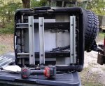
I purchased 2 lengths of shallow Unistrut with solid back from the Electrical Supply Company along with (12) 3/8" spring nuts. I installed 3 supports per seat attached to the bench frame. I then cut and attached 3 additional Unistrut pieces perpendicular to the other set that bolted up to the seat tracks. I had drilled 6 holes in the bottom Unistrut pieces to line up with the top Unisttruts. That allowed me to bolt the seats to the bench frame. (see pictures) Once the seats were attached I reinstalled the assembly into the truck and bolted it down.
 

Attachments

goldneagle

Well-known member
4,430
860
113
Location
Slidell, LA
Last Thursday I sat down and resigned a center console for the truck. I had taken the dimensions earlier in the day. I plan to make the center console fit around the bench frame that supports the bucket seats. Got a nice drawing done. The center console will include a radio/CD/mp3/USB and SD ports. It will also include (2) 6-1/2" speakers. I am also installing a small fuse panel, and (2) 12 volt outlets as well as a twin USB charging ports. I will also install 2 recessed cup holders. I also plan to install at least 1 toggle switch that will run my LED spot lights that will be attached to the brush guard. I may also install a RAM ipad holder at a later time.

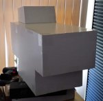
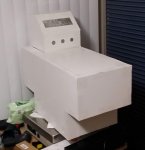
Friday I decided to construct a full scale model of the center console to make sure I was happy with the design and fit. I used white foam core poster boards. Upon first fitting I decided to make the radio housing taller. Here is the initial model and fitting:

Model_Initial_1.jpgModel_Initial_1a.jpgModel_Initial_Installed_1e.jpgModel_Initial_Installed_1c.jpgModel_Initial_Installed_1b.jpgModel_Initial_Installed_1a.jpg

Here are pictures of the modified center console after raising the radio enclosure:


Model_Final_1a.jpgModel_Installed_1.jpgModel_Installed_1d.jpgModel_Installed_1c.jpgModel_Installed_1a.jpgModel_Installed_1b.jpg
 

goldneagle

Well-known member
4,430
860
113
Location
Slidell, LA
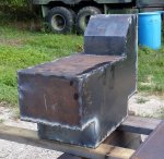
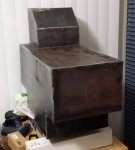
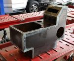
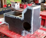
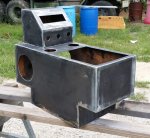
Well today I finally got a chance to work on the center console. I took out the saw horses and sheetmetal and started to measure and draw cutting lines. Once I had some lines drawn I brought out the new plasma cutter and started to cut the sheemetal (using a straight edge as a guide). The plasma cutter did a great job of cutting the sheetmetal pieces.

Once I got the sheetmetal pieces cut out i started to tact-weld the pieces together. It took a while but I got the whole center console welded together.

Took out the angle grinder with flap-disc and cleaned up all the welds. Will continue with the project tomorrow.
 

Attachments

goldneagle

Well-known member
4,430
860
113
Location
Slidell, LA
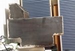
Today I cut all the openings into the console I build yesterday. That included the opening for the radio/CD player, (2) 6-1/4" diameter holes for the speakers, (3) 1-1/8" holes for the 12 volt power outlets, (2) 2-3/8" holes for the cup holders, 12" x 10" opening for the storage compartment lid. I am still deciding on the lid setup. Maybe some type of tray top on the lid to store sun glasses, change, cell phone and other items for easy reach. Suggestions are welcome. Here are today's pictures.
 

Attachments

tim292stro

Well-known member
2,118
39
48
Location
S.F. Bay Area/California
Perhaps a soft pocket inside the lid (can be fabric with velcro, and/or the wet-suit neoprene foam)? That way you can keep the console padded a bit... Hope the weather is not getting you too much.
 

goldneagle

Well-known member
4,430
860
113
Location
Slidell, LA
Had a computer crash this weekend -so today was the first day I could work on the center console.

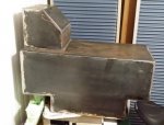
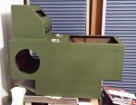
I took the console to my friend's shop in order to fill in the welded seams before painting. He had some compound that is finer than Bondo and volunteered to apply it on my project. He mentioned it had a really short set time and had the experience to apply it before it set up. All went well. Here are the pictures of the console after applying the sealer:Seam_Filled_1a.jpgSeam_Filled_1.jpgSeam_Filled_1b.jpg

I took the center console home and let it sit for a while to make sure the sealer was dry. I used 320 grit sanding discs on a DA Sander to sand the edges smooth. I than applied a coat of etching primer to the metal console. Here are some pictures:
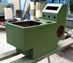
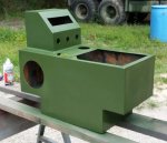
Primed_Console_1.jpgPrimed_Console_1a.jpgPrimed_Console_1b.jpg

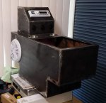
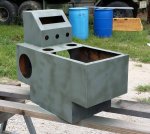
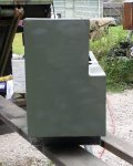
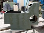
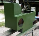
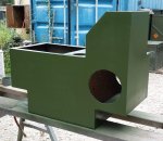
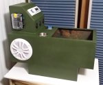
I caulked the inseams below the radio housing. I applied 2 coats of Rapco Green CARC substitute paint. Here are some pictures after painting:

Painted_Console_1c.jpgPainted_Console_1a.jpgPainted_Console_1.jpg

Some additional pictures:

Painted_Console_1b.jpgPainted_Console_1d.jpgPainted_Console_1e.jpg

And 1 more shot:

Painted_Console_1f.jpg
 

zout

Well-known member
7,744
154
63
Location
Columbus Georgia
I think from that console you will have to get your truck legally weighed again.

You may now be overwight.

Just kidding......good looking piece of building GE.
 

goldneagle

Well-known member
4,430
860
113
Location
Slidell, LA
I think from that console you will have to get your truck legally weighed again.

You may now be overwight.

Just kidding......good looking piece of building GE.
Thank you for the nice compliment it means a lot to me coming from a master fabricator. And thank you for visiting my humble thread. It was overweight as soon as I got into the truck rofl

Just the facts behind the build:

The sheetmetal of the center console is about the same gauge as the military truck tool (storage) boxes. (and I had it in stock)

The next gauge metal I have in stock is heavy duct-work which would have been too thin.

It is also easier for me to weld thick sheetmetal since it doesn't burn through as easy.
 

goldneagle

Well-known member
4,430
860
113
Location
Slidell, LA
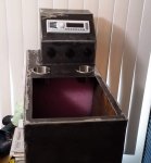
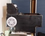
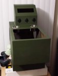
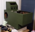
Today I managed to install the radio/CD player, speakers, power outlets and fuse panel. I also drilled a 1-1/8" hole under the console and installed a 3/4" Romex connector. I will feed the external power wires through this opening. I also wired all the components and the fuse panel.

When all was done I also tested the radio using a 12 volt transformer. Guess I got the wiring right....
 

Attachments

Top
AdBlock Detected

We get it, advertisements are annoying!

Sure, ad-blocking software does a great job at blocking ads, but it also blocks useful features of our website like our supporting vendors. Their ads help keep Steel Soldiers going. Please consider disabling your ad blockers for the site. Thanks!

I've Disabled AdBlock
No Thanks