• Steel Soldiers now has a few new forums, read more about it at: New Munitions Forums!

  • Microsoft MSN, Live, Hotmail, Outlook email users may not be receiving emails. We are working to resolve this issue. Please add support@steelsoldiers.com to your trusted contacts.


GP Module Theory of Operation

Status
Not open for further replies.

Warthog

Moderator
Super Moderator
Steel Soldiers Supporter
13,775
227
63
Location
OKC, OK
And I always thought it was the Magic Smoke Genie that made it work.

If you let the Genie out then it wouldn't work anymore.....:p


Thanks for the write up.
 

dstang97

Well-known member
1,859
30
48
Location
Clover, SC
Attn: antennaclimber

When are you going to make some cards for us? I just saw a thread about you making your own card. I'm first in line.
 

antennaclimber

Moderator
Moderator
Steel Soldiers Supporter
1,350
885
113
Location
State College, PA
The monitor wire should be connected to the glow plug side of the relay. Not the resistor side.
The schematic is incorrect.
Karl
 
Last edited:

bigflew

Member
202
15
18
Location
alpena michigan
this theory of operation has been a great help. all my glow plugs went out at the same time and I havent quite figured out why yet so I have a couple questions.
1. is the glow plug card reciving 12v. or 24v from the fuse box and sending 12v or24v to the relay.
2. the theory is refering to 12 v at the glow plugs I hope this suposed to be 24v or I have a problem.
 

antennaclimber

Moderator
Moderator
Steel Soldiers Supporter
1,350
885
113
Location
State College, PA
Big,
The glow plug card receives 12 volts from the vehicle electrical system for power.
The glow plug relay has a constant positive 12 volts applied to one side of the relay coil, the GP card simply provides a ground to the other side of the relay coil to close the contacts.

The GP's are powered from the 24 volt side of the electrical system through a resistor mounted on the fire wall. The resistance of the resistor and the resistance of the GP's will lower the 24 volts to 12 volts at the glow plugs. If one or more of the glow plugs go high in resistance (open) the voltage will increase at the remaining good glow plugs. A simpler way to power the GP's is to bypass the resistor on the fire wall and feed the GP relay from the 12 volt side of the electrical system. This will prevent the GP's from seeing excessive voltage.

I hope this helps you out.

I like the digital camo paint job!
Karl
 

antennaclimber

Moderator
Moderator
Steel Soldiers Supporter
1,350
885
113
Location
State College, PA
I have updated the color GP schematic attachment.

The temperature sensor wiring is now correct and a couple of the wire descriptions were not properly drawn.

The original schematic in the TM has 4 errors in it.
Karl
 

jdemaris

New member
188
6
0
Location
NY
. . . so why the 24v glow plugs?
No 6.2 ttrucks or Blazers, civilian or military use 24 volt glow-plugs. The plugs themselves are designed to work within a voltage range of 9 - 14 volts.

There is a strict relationship between how fast a particular brand of glow plug heats up -and how long it will heat before the controller shuts it off. That is why OEM controllers get a little "out of whacK" when different glow plugs are used with different amp-draws and heat times. Different brands or types will result in different controlled heat-cycles.

All the AC Delco designed systems for 6.2 diesels work like this (when all is correct). The controlller is designed to sense a certain amp draw when all eight glow plugs are working as designed. If one or two burn out, the total amp draw is less, and voltage gets higher . To prevent immediate plug burn out, the controller shortens the cycle time to protect them. This only works to a certain point.

To put it simpler, if a few plugs go bad, the heat time should get shorter to protect them.

The same happens if you installl a different type plug that has less amp draw.
 

acesneights1

Member
1,449
21
20
Location
CT
Any reason this system could not be replaced with a controller from a civvy 6.2 and wired to the front battery ?
 

swinters

Member
56
9
8
Location
Olympia, WA
i need a chip anyone know were i can find one mine burned up and truck only has 12k from what i have found out so far the m1028 daullys are a rare find and its single cab short bed with a utility box says it was a military postal unit
Hopefully you've found one by now but if not go to cucvelectric.com. Many times the board burning out is a symptom, not the problem so make sure you do the checks they have where you pull the board and run tests. It only takes a multimeter. Make 100% sure your grounds are good. Also, Wait for the WAIT light!! According to the engineers at GM and TACOM the most common cause by far of controller board failures is trying to start the truck while the WAIT light is still illuminated. As one of the engineers once told me "When it says to wait it ain't jokin' and while it may not fail right away it don't forget"...
 

Warthog

Moderator
Super Moderator
Steel Soldiers Supporter
13,775
227
63
Location
OKC, OK
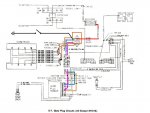
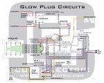
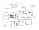
Just to clear up some confusion.

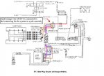
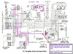
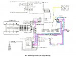
The GP Controller card only controls the grounding of the coil for the Glow Plug Relay. The little "light blue" wire on the relay.

The "pink/black" 12v hot wire on the relay coil, is controlled with the ignition switch and the fusebox. It is hot whenever the key is on.

Circuit #39 in the diagrams.

It should be reading battery voltage.

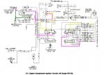
One of the BIG issues is that the fuse that feeds this wire is also feeding many other things. Some of them are:

Seatbelt buzzer
Water in fuel solenoid
Cold advance switch - Cold Advance Control and Fast Idle Solenoid
Instrument cluster circuits- Temp light, Low Coolant light, Brake light, Fuel guage
Glowplug Relay and GP Controller

That is ALOT of power for single circuit. If any of this circuits are draining power due to dirty connections, then the voltage will drop.

So if you are reading less than battery voltage (i.e. 12.4v) there is more issue to resolve than a bad GP controller.

A low voltage for the GP Relay coil may cause a chattering of the relay. It may depend on if you you are using a cheap $9 eBay relay, a S603 or the NAPA ST-85.

As usual, YMMV.
 

Attachments

Last edited:

rodman68

New member
55
0
0
Location
olympia, Wa
Does anybody know what the voltage would be on the output of the glow plug relay when glow plugs are cycling when all is good? Been having problems with the m1009 starting cold removed the wellmans didnt know they were not a good glow for these vehicles. Four of them were bad replaced all with 60g started fine at first but a couple days later having starting issues again. Checked all glow plugs were ok, noticed the alternator belts were loose tightened them. When the glow plugs cycle the voltage at the output of the glow plug relay starts a 9.0 vdc and slowly cilmbs. Thinking the batteries might be a little week due to the loose belts and this vehicle is used for kids to goto school that is very close to home not enough time for the batteries to recharge.
 
Status
Not open for further replies.
Top
AdBlock Detected

We get it, advertisements are annoying!

Sure, ad-blocking software does a great job at blocking ads, but it also blocks useful features of our website like our supporting vendors. Their ads help keep Steel Soldiers going. Please consider disabling your ad blockers for the site. Thanks!

I've Disabled AdBlock
No Thanks