• Steel Soldiers now has a few new forums, read more about it at: New Munitions Forums!

  • Microsoft MSN, Live, Hotmail, Outlook email users may not be receiving emails. We are working to resolve this issue. Please add support@steelsoldiers.com to your trusted contacts.


Grove Crane Winch for HEMTT's, MTV's, LVS and PLS.

tobyS

Well-known member
4,820
815
113
Location
IN
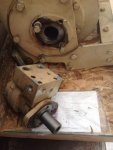
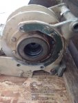
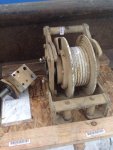
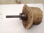
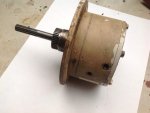
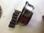
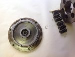
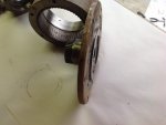
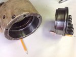
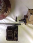
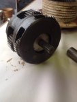
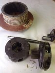
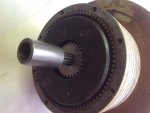
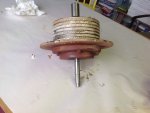
I purchased an LMTV hydraulic winch on line (edit...it's a Grove Crane winch). It appears to have places where air lines may have been removed that go into what I thought was a gear box. Now I think that part is a brake or some type of clutch.

It's physical size is smaller than I expected. Was there more than one size winch on an LMTV? I read the LMTV winch could have 300' of 1/2" cable. This one won't hold near that much.

Is there an overall explanation or TM that explains what is what on this winch and how it operates? I understand the hydraulic cross pilot operated check to hydraulically lock it and what appears to be a relief valve, but there are three lines for air that I don't know about.

Edit; this winch is a Grove Crane winch...not an FMTV.
 
Last edited:

Suprman

Well-known member
Supporting Vendor
6,842
654
113
Location
Stratford/Connecticut
LMTV winch is hydraulic. 4x4 has a 10k winch and 6x6 would have a 15k winch. Other vehicles have had the same style side mounted winch also. Post pics.
 

tobyS

Well-known member
4,820
815
113
Location
IN
The unit that I called a gearbox with the long shaft allows the shaft to turn one direction and like a sprag clutch, locks in the other direction. The outer large gear is fixed, does not turn. Thus all the gearing must be inside the winch drum and this unit has brakes or one way clutch's, not gearing. It must have air operated pistons.
 
Last edited:

tobyS

Well-known member
4,820
815
113
Location
IN
My mistake then. The ad did not exactly say it was from an LMTV.

I guess now I get to tear the brake apart and see how it works and what I need for control. While I think it's air, it may be hydraulic that operates the outer unit (brake).
 

tobyS

Well-known member
4,820
815
113
Location
IN
Okay, I'm convinced not FMTV. It's too small, but probably fine for a small crane. It's not as large as I thought.
 
Last edited:

tobyS

Well-known member
4,820
815
113
Location
IN
I wish I had the rest of it (the entire crane)....but it might be a bit big on a mid mounted 4x4 deuce.
 
Last edited:

tobyS

Well-known member
4,820
815
113
Location
IN
Moderator, please change the title to "Grove Crane Winch".

I still have to determine how it operates. If anyone has pictures or a diagram of the connections to the brake part, please post them.
 
Last edited:

Gunzy

Well-known member
1,769
65
48
Location
Roy, Utah
That is deffinately a grove crane winch from a HEMTT. It is only rated to lift 5400lbs max. So unless you build a crane it is a bit useless.
16998190_10206279158298300_7758079983256569513_n.jpg
Here are pics of a frame mounted winch on my HEMTT that is a 20K lbs unit. The LMTV/FMTV setup is very similar.
22815366_10207832266645038_2408781206040654293_n.jpg
 

tobyS

Well-known member
4,820
815
113
Location
IN
Actually Gunzy, I made a mistake that seems to be working out okay. Buying from a picture they look a lot alike. But it's clear now that it is the crane winch.

Along the way in planning this project I started thinking that I had an FMTV winch coming...the first mistake. Then I was going to mount it on the front and use a pipe gin pole....that was likely to result in front suspension overloading. Then I went to the rear with the gin pole and winch (which wasn't a bad option) and planned to use the LMTV bed (pictured)...another change in the plans.

I want to make the M35A3 into a 4x4. While looking at gin poles and winches, Gimpy and GG and others linked some really interesting designs. A crane at the end of one link was very much like my boomtruck, center mounted and swivel. I began rounding up parts for a similar design, using what I have on hand as much as possible. On the boomtruck, the crane has additional frame lapped to the side of the OEM frame. I decided that before I fab a crane, I can make new suspension mounts for the 105 springs with a long piece of 1/4 plate, formed into an 11 x 3 x 8' L angle. Then the frame support is mounted lapping the frame and with the bottom 5" below the existing frame. Then gussets and cross pieces will be welded in and the spring mounts added.

From what I can tell from GG and others, the 5" drop works properly with the M105 springs and frame mounts to give a slightly higher rear end than front when unloaded.

I'm leaving the rear back axle about where it is in relation to the frame or maybe a couple inches forward. I decided buying an M105 bed is the route I take instead of using my LMTV bed. I want shorter, not longer than the oem bed.

I know this is long, but now I'm focused on a center mount crane. The winch is obviously suited to the task. I have a surplus of NOS 2"x24" stroke cylinders, so envision a crane with 2 lifting, much like an excavator. Each gives me 7500# at full 2500psi, so the rating on the winch is about right to match my boom lift capacity.

My mistake about the winch will work out just fine. I have a tendency to overbuild, so keeping this crane light and compact may be difficult. This mistake keeps me at the right scale, I think.
 

Attachments

tobyS

Well-known member
4,820
815
113
Location
IN
The winch is entirely apart. It has a one way clutch that is splined with the steels of a hydraulic clutch. It is hydraulic, not air. There is one piston with springs behind it that force the clutch plates to engage and stop rotation of the sprag part, which is splined to the clutch steels.

I'm assuming the one way rotation (free) is the pull side of the winch, so it can come in without the brake affecting it but not allow it to go out without the clutch pack disengaging.

There are indeed three (control) ports into the brake unit, two of them would push the piston against the springs and release the braking and the other would act with the springs to hold the clutch in place (not allow it to turn).

I'll get the Ipad and take some photo's of the internals and put them up in the next post.

Like everything I get that was military, there was some water in it that left some rust. Not bad really and the gears are all sharp and new looking.

The company sold it showing it together. Someone attempted to take the fairlead off and stopped. He left all the bolts off and the brake unit pulled out and was hanging. Thankfully they took photo's that showed it "as shipped", which were different than the fleebay pictures and showed someone had messed with it. Hanging by the shaft for 1000 miles bent the shaft. It didn't mark the steel, but the shaft was bent. Before I took it apart, I made a deal with the seller for a significant discount due to the damage.

I have a flat table where I found the high spot of the bare shaft and used a heavy piece of CR to bring it back. Three solid hits and it looks straight again with no visible marks. Now it's time to re-assemble and I'm not confident in putting the one way clutch in in the correct rotation.
 

tobyS

Well-known member
4,820
815
113
Location
IN
Here is the disassembled brake. The shaft goes through and is keyed to the one way clutch that is splined to the friction portion of the clutch. The steels are splined to the outer housing. When compressed by the spring, they stop the shafts rotation, in one direction. The springs are in the piston,so hydraulic pressure against it directly pushes against the springs to release the brake clutch.

This is entirely a wet system, hydraulic actuation.

Not that I would do it, but relying on the hydraulic motor for braking, with it's cross port flow controls on the unit, I might be tempted to leave the key out, rendering the mechanical brake inoperable and NO hydraulic lines to it...and stick some permanent grease in it.

That would eliminate my dilemma of which way the clutch was installed. Note there is no freewheel on this winch.
 

Attachments

Last edited:

tobyS

Well-known member
4,820
815
113
Location
IN
For hydraulic actuation of this brake, or rather the release of it, there are ports that allow flow to the piston that you can see in the last photo. Actually there are 2 sets of three ports and some are plugged.

One set puts flow into the back of the piston on the spring side. That would provide hydraulic actuation to put more pressure than the springs apply on their own. That set of ports increases braking effect and is most near to the outer cover.

The next set of ports puts pressure to the other side of the piston to release it against the springs. This is the port that needs pressure to release the brake. I have no idea about this control line PSI, but I'm guessing at 300. There are another set of ports that act on the narrowed down section of the piston, against the springs and it also seems to provide pressure to bathe the clutch in oil. Pressure on that most inner port would release the brake but I'll look again for any other functions.
 

tobyS

Well-known member
4,820
815
113
Location
IN
GROVE crane winch

I've reassembled each section about 3 times now.

Since it's apart, it gets new o-rings for the piston and the case. Cost of 6 o-rings $8 and a few days. They are (2) 6" OD x 5 3/4" x 1/8", (2) 6 1/4 OD x 6" ID x 1/8" and (2) 3/32" x 6 3/4" OD, all are 70 duro.

There was silicone everywhere that if not completely cleaned away, might prevent sealing again. I've seen places the silicone gave water a path to get in when setting. That is not surprising on flat surfaces against each other, but this needs a good hydraulic seal, so I want a clean smooth surface to mate against. Many places I sand and red prime. I reassemble with red grease on about every surface, no silicone.

I have to revise my estimate of the hydraulic fluid to fill it, brake section and gearbox at 2 quarts.

I noticed there is a brake section (only) of this same winch for sale on fleebay for over $1,200...wow!

In the first assembly of the one way clutch onto the shaft, I had it going the wrong direction. I had to assemble the gearbox, shaft and one way clutch to get the direction correct...stopping it from pulling out.

I'm hoping someone can tell me the system pressures for the power and the control. At first I thought to 300# but I am reducing that estimate. Another member said some systems have a 195# pump, but it could be lower.

While I thought the block on the hydraulic motor had flow control to stop fluid, the only apparent "control" appears to be related to pressure. A crane hydraulic diagram would be very helpful.
 
Last edited:
Top
AdBlock Detected

We get it, advertisements are annoying!

Sure, ad-blocking software does a great job at blocking ads, but it also blocks useful features of our website like our supporting vendors. Their ads help keep Steel Soldiers going. Please consider disabling your ad blockers for the site. Thanks!

I've Disabled AdBlock
No Thanks