• Steel Soldiers now has a few new forums, read more about it at: New Munitions Forums!

  • Microsoft MSN, Live, Hotmail, Outlook email users may not be receiving emails. We are working to resolve this issue. Please add support@steelsoldiers.com to your trusted contacts.


Gun Ring M36 / M49

blisters13

Active member
Steel Soldiers Supporter
454
68
28
Location
Beaumont in SoCal
Hi All:

I am starting this thread specifically for the M36 / M49 machine gun ring, as will be installed on my 1968 Kaiser-Jeep M35A2.

I understand they were installed in military units, but I have not seen proof.

This ring weighs about 80-90 pounds, which makes it MUCH lighter than the M66 model; additionally, it was designed to support the M2 .50 caliber machine gun, so it is an ideal model to install when trying to avoid damaging the cab.

Some of the material I will be posting I had previously posted in a thread dealing with installing an M66 ring; I realized after several posts that that was highjacking the thread, so I stopped posting that info there.

Apologies,
-Ken
 
Last edited:

blisters13

Active member
Steel Soldiers Supporter
454
68
28
Location
Beaumont in SoCal
I have downloaded a copy of TM 9-1005-245-14 manual from 1973.

The great thing about this edition is that, starting on page 9, there is a series of illustrations of the different models of the time!! Starting with the M36, there are eleven ring mounts shown.

If anyone wants a copy, contact me; it's a pdfslide.net file which can be opened in Adobe. I tried to re-use the link, but it expires so no go. It's just under 6 megs.
 

blisters13

Active member
Steel Soldiers Supporter
454
68
28
Location
Beaumont in SoCal
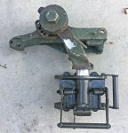
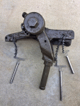
I received a carriage/trolley for the M44 (M36?) ring; it was missing the four side wheels which are removed and reinstalled when removing/replacing the carriage, and it was missing two bottom wheels.

The wheels are actually common bearings.

I made four replacement bolts (out of 5/8" bolts, turned down and rethreaded), two missing bottom wheel pins, and bought the six "wheels".


IMG_8069.jpg


IMG_8065_web.jpg


As can be seen, a 1/2" bolt will not have a large-enough diameter to seat the bearing inner bore.
A 9/16" bolt will still be too small. Possibly a 1/2"-20 bolt with appropriate bushings could be used.
Of course, if they can be found, the proper bolts would be best.


IMG_8060_web.jpg


Here, I'm checking the fit (bottom view). It's a little tight in some spots (doesn't want to roll through) so thorough rust removal is indicated.

As may be noted by experienced people, I also made the missing bottom clamping bolt/handle. Normal fine-thread 1/2"-20 nuts thread onto the "wheel" bolts.
 
Last edited:
blisters13

Active member
Steel Soldiers Supporter
454
68
28
Location
Beaumont in SoCal
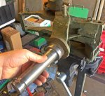
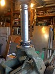
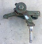
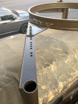
I was given a .50 cal cradle by my friend Mike (to whom I sold my M715), but it had the shorter, tapered pin which does not fit the trolley/carriage that I have.

I made a replacement pin, cut off the original with a port-a-band saw, and welded-on the replacement.

I believe it will support firing a .50 cal for a short time, but I know it WILL work carrying a replica, no problem. I used 70,000 psi filler wire.

IMG_8071_web.jpg

IMG_8076_web.jpg

IMG_8085_web.jpg

IMG_8083_web.jpg

If I was sure this would be supporting a firing .50 cal, I would spend the time and money to get the original, correct one. This one cost me just a few bucks for the steel and welding material (wire, gas, and electricity).

When it's up on the truck, it'll look fine (I hope!).
 
Last edited:
blisters13

Active member
Steel Soldiers Supporter
454
68
28
Location
Beaumont in SoCal
The WWII ring design is very different from the later M66 design, so dimensions are not likely to be similar.

Can you please ask again what you need?
 

Dragoons17th

New member
2
1
3
Location
PA
Sure, I need to know the internal dimension (width inside the circle) of a MG ring. Not sure what size I need yet.
I'm building a 1914 pattern Rolls-Royce armoured car on a '25 Rolls-Royce chassis (virtually identical) and I'm currently exploring the idea of using a MG ring for the turret rotation.
The M68 at (I believe) 48" I.D. is a likely candidate for the project, but I need to know what else might be suitable. Always better to know the options before starting the search.
After studying pics of the 2 survivors out there and other random online interior pics of RRACs of which there are very few, it appears that the 'bearing' design was left up to the various assembly shops to design and fabricate, in other words, no two pics show the exact same design. Regardless of design, they were noted for losing their turrets in severe conditions.
 

blisters13

Active member
Steel Soldiers Supporter
454
68
28
Location
Beaumont in SoCal
Ok; the WWII M36/M49 ring is a single piece with no bearings. The gun was mounted in a cradle for elevation and left-right motion which was mounted to a single carriage/trolley for rotation of position within the ring.

There are no moving parts of the ring itself.

This model won’t be suitable for your purpose.
 
Last edited:
blisters13

Active member
Steel Soldiers Supporter
454
68
28
Location
Beaumont in SoCal
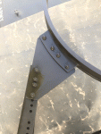
MANY THANKS to Will Wagner, who has spent the time to make most of the tedious dimensions necessary to get this going!! :grd:

I have started the left rear leg....


IMG_8469_web.jpg

Blank brackets ($49 each, sheared and bent)
Drilled holes based on M49 ring pattern


IMG_8468_web.jpg

Test fit (yes there will be adapter plates to make
and install)


IMG_8479_web.jpg

Tube welded on; needs finish at
joint. Also cut 60" long, not 47"
as factory to get full clamp length
at cab back brackets


IMG_8474_web.jpg

The triangular stops: sheared from 3/16" x 1/2" bar
 

blisters13

Active member
Steel Soldiers Supporter
454
68
28
Location
Beaumont in SoCal
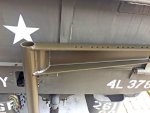
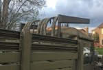
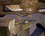
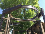
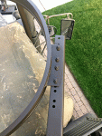
I have finished the two rear legs/brackets and installed them

IMG_8565_web.jpg

IMG_8563_web.jpg

IMG_8722_web.jpg

IMG_8720_web.jpg
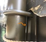
Note that in order to get the canvas top to fit between the legs and the back of the cab, I added a 1/4"-thick
spacer from the top U-bolt down to the bottom of the leg. I also cut out the rope loop which was centered
on the leg location. This cab top is a modern vinyl one, not cotton canvas. The spacer is made by cutting a
piece of steel pipe, same as the leg tube, in 90 degree width.
 
Last edited:
  • Like
Reactions: 98G

blisters13

Active member
Steel Soldiers Supporter
454
68
28
Location
Beaumont in SoCal
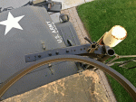
And.... for a nod to the past....
IMG_8557_edit.jpg

Will Wagner familiarizing me with the truck I bought from him, at time of sale
 
Last edited:
  • Like
Reactions: 98G

blisters13

Active member
Steel Soldiers Supporter
454
68
28
Location
Beaumont in SoCal
Sooooo....

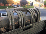
As I have been working on the ring and hardware, I have also been collecting gun mount parts.

To that end, I purchased an ammo box tray, which turned out to not fit my equilibrator gun cradle (that figures!).

So, I made an adapter.

IMG_8697_web.jpg
Part at upper view is the side of the cradle; it has a pair of 1/4" slots at an angle.
Part at lower view is the ammo box tray, which has a slot on the edge (which is slightly under 1/4")

IMG_8699_web.jpg

IMG_8700_web.jpg
I used 3/16" steel angle for the tray side, and 1/4" flat bar for the cradle side. A piece of 1/4"
by 3" bar spans the two slot adapters.

IMG_8704_web.jpg
Note: The tray has a cam lock so that it is less likely to bounce out. I need to
add something to the adapter so it is secured to the cradle.
 
Last edited:
blisters13

Active member
Steel Soldiers Supporter
454
68
28
Location
Beaumont in SoCal
PART WEIGHTS

I weighed the following parts on a refrigerant scale:

RING: 107 lbs. 12 oz.
CRADLE equilibrator style: 32 lbs. 11 oz.
CARRIAGE /trolley: 25 lbs. 8 oz.
AMMO CAN TRAY: (with my adapter) 13 lbs. 16 oz.
FRONT LEG / BRACKET: 37 lbs. 1oz.
REAR LEGS (longer than factory): 42 lbs. 3 oz.

TOTAL (estimated including hardware, excluding rear cab brace plate): 304 pounds(!)

Total without the carriage and cradle (just driving down the road): approx. 230 lbs.

This does not include a gun, ammo, can, or the two extra can brackets I have not bought.
 
Last edited:
blisters13

Active member
Steel Soldiers Supporter
454
68
28
Location
Beaumont in SoCal
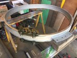
I have cleaned and kinda reconditioned the ring; painting it now:
892983AA-6D62-4390-B704-AA8C1B7A3ADE.jpeg
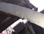
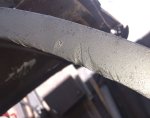
The carriage would not traverse around, and got stuck in several spots even after smoothing all the rough spots with a 5 1/4” grinder flap wheel. I ended up grinding down several high spots and now it’s fine.

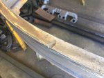
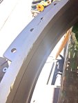
The following pics show surface defects which I removed. The high spots I had to grind down were found after the surfaces had been smoothed.

542C5963-D85D-4E35-AE98-E595FEC95BEC.jpeg

E064D2E0-5DF9-4A39-AAD8-E87B8DD16FC5.jpeg

7EAE9129-4EF4-43A8-B921-B03964C3F3D6.jpeg

C29C5AA9-C7F3-4AA9-9A51-C2EAF5AAFEDA.jpeg
 

Attachments

Last edited:
blisters13

Active member
Steel Soldiers Supporter
454
68
28
Location
Beaumont in SoCal
Some things I found interesting:

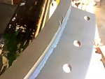
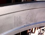
1. The ring is a rolled piece of bar which is butt-welded:
BC122C01-3143-4E48-811C-344AFFFD76F6.jpeg
The lines indicate a clamping fixture and the butt weld can be seen.

2. The ring I have, never had a riveted ID plate, but does appear to have a serial number:
1A16FA18-9D35-493C-937D-74DF9E01A05E.jpeg

3. It has the cool U. S. Army Ordnance Corps symbol stamped in an ear:
254686D1-604C-4DC2-B271-14B104800ABC.jpeg
 
Last edited:
blisters13

Active member
Steel Soldiers Supporter
454
68
28
Location
Beaumont in SoCal
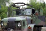
The ring is completed and installed:
IMG_9012_web.gif

IMG_9126_web.gif

IMG_9127_web.gif
This adapter plate is just a guess, shaped to support as best as I could get it.

IMG_9128_web.gif

IMG_9129_web.gif

IMG_9130_web.gif
NOTE THAT THE BOW CORNERS CANNOT BE STORED NORMALLY :(


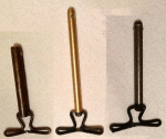
Also, I made a set of cradle pins:

IMG_9318_web.gif

IMG_9317_web.gif
An original set...

m35a2-m66-m66-ring-mount-legs_1_c5ded5f95a462a107ea464956fc24c18.jpg
A "heavy" M66 ring installation, shown for comparison. I do not have the vehicle owner's info.
 

blisters13

Active member
Steel Soldiers Supporter
454
68
28
Location
Beaumont in SoCal
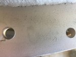
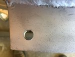
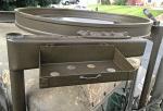
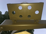
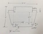
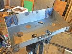
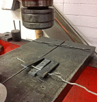
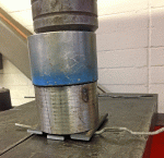
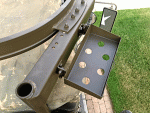
I have not been able to find any of the spare ammo trays for sale, so I made one:
IMG_0101_web.gif

IMG_0102_web.gif

IMG_0104_web.gif

IMG_0084_web.gif

Solid lines denote cuts; dashed lines denote bends.

IMG_9903_web.gif

IMG_9900_web.gif

IMG_9901_web.gif

IMG_9902_web.gif
The wire is 5/32" 7018 welding rod. The bars are 1/4" x 1" x 4".

Since I didn't have an original, the design and size are not exact; however, the inside dimensions
I took from the ammo tray that I have for the equilibrator mount.

One thing missing from my design is a spring clip at each end. Instead, I made bars which will keep
the common 1" webbing strap (used for everything) in place.

The drain holes were punched with a 3/4" (trade size) electrician's knockout punch set.

The hardware is 3/8".
 

Attachments

Last edited:
2deuce

Well-known member
1,444
108
63
Location
portland, oregon
There was a cab stiffener kit for the M66 ring. I think I would want that on there, if I had any ring up there, but I don't know the weight difference.
 
Top
AdBlock Detected

We get it, advertisements are annoying!

Sure, ad-blocking software does a great job at blocking ads, but it also blocks useful features of our website like our supporting vendors. Their ads help keep Steel Soldiers going. Please consider disabling your ad blockers for the site. Thanks!

I've Disabled AdBlock
No Thanks