Warthog, and others, thank you for the reply. That's the same information I just now found. We just relocated so finding all my docs can be a challenge.
As always I knew this board and it's members would be reliable help.
I'm having the alternator rebuilt and will reinstall it later this week.
I'll post who re-built it for me after success. Maybe someone else will need alternator help in the future.
Just an FYI, I had the exact same issue.. volt gauge always in the yellow.
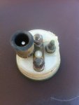
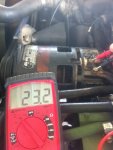
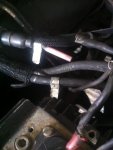
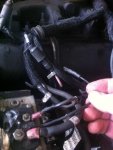
I started the truck, warmed it up, turned the headlights on, engaged the accelerator 'cruise control' handle to keep it just above idle, removed the set-screw next to the wire terminals on my prestolite alternator, plugged my Fluke meter from ground to hot, and spent about 20 mins trying to 'breathe' on the adjustment screw with my screw driver to adjust the voltage to within spec. (28V)
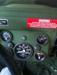
(Just followed the TM below) & now i'm in the green & everything is perfect.
1. Using hex-head driver, remove pipe plug (12).
2. Connect battery ground cable (para. 4-73).
3. Start engine (TM 9-2320-280-10).
4. Raise engine speed above idle.
5. Put a load on the alternator by operating driving lights (TM 9-2320-280-10).
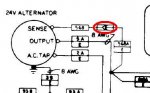
6. Using a multimeter, check alternator (15) output voltage. Connect black test lead to ground
lead 3B (1
")
. Connect red test lead to lead 5A (16). Output voltage should be 28 volts ± 0.5 volts. If
adjustment is required, go to step 7. If no adjustment is required, go to step 11.
7. Turn adjusting screw (17) counterclockwise to increase voltage or clockwise to decrease voltage.
8. Turn off driving lights (TM 9-2320-280-10).
9. Return engine to idle.
10. Stop engine (TM 9-2320-280-10).
11. Apply sealing compound to pipe plug (12) threads. Using hex-head driver, install pipe plug (12) and
tighten to 30-40 lb-in. (3-4 N•m).
12. Remove battery ground cable (para. 4-73).
13. Seal terminal connections using adhesive sealant.
14. Install terminal cover (7) on alternator (15) with two lockwashers (5) and screws (6).


 77 KB Views: 68
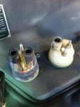 70.6 KB Views: 58