• Steel Soldiers now has a few new forums, read more about it at: New Munitions Forums!

  • Microsoft MSN, Live, Hotmail, Outlook email users may not be receiving emails. We are working to resolve this issue. Please add support@steelsoldiers.com to your trusted contacts.


Hmmwv no power to alternator

Mogman

Moderator
Staff member
Moderator
Steel Soldiers Supporter
5,916
8,237
113
Location
Papalote, TX
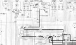
The reason the fan will not run is because the voltage going to the 60A alt (wire 5A) is controlled by the same relay the powers the fan and it is fried because the 100A alt has been charging the batteries through it.
 

Mogman

Moderator
Staff member
Moderator
Steel Soldiers Supporter
5,916
8,237
113
Location
Papalote, TX
The ign. sense wire 568 and the old 60A charge wire 5A are both powered by the same relay, when converted to 100/200/400A alt. the wire 5A should go to ign. sense and the wire 568 should be taped off and abandoned.
The reason the 5A is switched to ign. sense is because the wire 568 will not handle the additional ign. sense current required by the 100/200/400A alternator
 

Mogman

Moderator
Staff member
Moderator
Steel Soldiers Supporter
5,916
8,237
113
Location
Papalote, TX
The relay that is burned up in your start box is easy enough to replace but of course you need to run the 100A output terminal directly to the batteries with a large enough wire to handle 100A
 

Mogman

Moderator
Staff member
Moderator
Steel Soldiers Supporter
5,916
8,237
113
Location
Papalote, TX
Here is how the 200A is wired, the 100A should be wired the same way, notice that 568 and 5A both go to the ign. sense terminal BUT you will notice the X on the 568 wire, that means it is not connected in this application.
EDIT, what this chematic does not show is there should also be a heavy wire going from the 14V tap on the regulator to the connection between the batteries to balance the battery charge, a #6 wire would be sufficient here.
 

Attachments

Last edited:

Milcommoguy

Well-known member
Supporting Vendor
1,653
2,098
113
Location
Rosamond, CA
The relay that is burned up in your start box is easy enough to replace but of course you need to run the 100A output terminal directly to the batteries with a large enough wire to handle 100A
Hello Mogman, The way I read it... Not so much the sense current requirement, but looping the alternator output / charge current back thru the box. Those # 8 ga pins are rated at 72 amps. Short run of number 8 ga wire could ?? handle it for a while. "RUN" contractor / relay rated at 125 continuous, more intermitt. Not an ideal condition.

Trying to help with the hack , CAMO
 

Mogman

Moderator
Staff member
Moderator
Steel Soldiers Supporter
5,916
8,237
113
Location
Papalote, TX
Hello Mogman, The way I read it... Not so much the sense current requirement, but looping the alternator output / charge current back thru the box. Those # 8 ga pins are rated at 72 amps. Short run of number 8 ga wire could ?? handle it for a while. "RUN" contractor / relay rated at 125 continuous, more intermitt. Not an ideal condition.

Trying to help with the hack , CAMO
That was my point, not running the 100/200/300A charging current through the run relay/contactor.
The instructions are very clear about abandoning the #568 wire and using the 5A for ign. sense in the 200A installation instructions.
The 100A uses the same regulator and should be wired the same way as the 200A
 

Mogman

Moderator
Staff member
Moderator
Steel Soldiers Supporter
5,916
8,237
113
Location
Papalote, TX
Those contactors fail all the time on 60A installations, pushing it to 100A would not be wise.
 

John Perry

New member
3
1
3
Location
Kings Hill Point, Calif.
The 60A alternators output went through a start box relay so there was no voltage on the output terminal unless the vehicle was in the run position.
When it was converted to 100A there should have been a large wire run directly from the alternator output terminal to the batteries, the start box relay cannot handle the output from a 100 or 200A alternator.
Your truck seems to be using the old 60A charge wire (5A) which is incorrect.
Makes scene now as you explained it. The 1986 M998 was competly rebuilt back in 2011, upgraded to a 6.5 engine by the Army. I think I will now replace that heavly wire coming from the Alternator directly to the batteries. That may explane why I am having issues with my control boxs. Too many amps trying to travel through it. I work on Aircraft Avionics, i will apply my Aircraft knowledge to this issue now. Thanks for the explanation!!!
 

John Perry

New member
3
1
3
Location
Kings Hill Point, Calif.
2 1/2 years later and getting thrown under the bus. Then why post the same thing I was saying. Sorry couldn't answer all your questions. Mogman is likely correct your 100 amp unit was hacked in and control box is not going to be happy. And for a first post... sound like you have it all figured out.

Covid is a real thing, CAMO >>
[/QUOT AND I could argue about the Covid bullshit and the mandatory vaccination using an experimental vaccine . It was not a hack job as you suggested, it was done when the M998 was completely rebuilt back in 2011 for the US Army. Not sure why you thought the bus got you. I have corrected the wiring to the IGN terminal, will be replacing the wire going f Alternator to the battery set next.
 

Mogman

Moderator
Staff member
Moderator
Steel Soldiers Supporter
5,916
8,237
113
Location
Papalote, TX
Even if I had a 60A now I would run the alt output directly to the batteries, the only reason this was done was in the original (60A) configuration the PCB (protection control box) would protect the system in-case somebody connected the batteries backwards.
In the case of the alternator it would simply not activate (close) the run relay protecting everything wired to the run relay including the alt.
Of course this all went out the window when they went to the higher amperage alternators that required by-passing the PCB.
That is the only reason the original 60A was not connected directly to the batteries like just about every other alternator in the world.
Because everything has to be backwards compatible they never went back and re-designed that horrible system, all the PCB/EESS box should be is a glow plug controller, in fact in the civy version of the 6.2/6.5L vehicles the TSU did all the glow plug timing/control and it simply controlled a relay connected to the glow plugs.
 
Top
AdBlock Detected

We get it, advertisements are annoying!

Sure, ad-blocking software does a great job at blocking ads, but it also blocks useful features of our website like our supporting vendors. Their ads help keep Steel Soldiers going. Please consider disabling your ad blockers for the site. Thanks!

I've Disabled AdBlock
No Thanks