• Steel Soldiers now has a few new forums, read more about it at: New Munitions Forums!

  • Microsoft MSN, Live, Hotmail, Outlook email users may not be receiving emails. We are working to resolve this issue. Please add support@steelsoldiers.com to your trusted contacts.


Installing instruments!!!

commandojd

Member
64
1
8
Location
Deshler OH
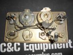
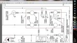
I am in the process of restoring my m35 and just got it back from the paint shop. I had the instrument panel removed and disassembled for paint and repairs. Unfortunately, the guys at the paint shop unintentionally removed all my markers I put on all the connectors in order to properly reinstall my cluster. I know the obvious guages such as the tack, spedo and pressure connect, but I cant seem to remember where the remaining wires connect to. I am confused because my spider ground harness that screws onto the back of one of the voltage gauges has 5 connectors but only has three gauges to connect to...where do the other two connectors go?? And which wires connect to the other guages/ dash lights?? I looked for a TM but was not successful in finding the info I need. Does any one know what # wires connect where? and where the ground goes?? Any help would be awesome!!
 

commandojd

Member
64
1
8
Location
Deshler OH
Not sure if I am seeing what you are talking about...All I found was a TM that had a picture of the instrument panel...but not the rear section of it where the wires connect???
 

welldigger

Active member
2,602
15
38
Location
Benton LA
At the top of the deuce main forum in the stickies look for a thread called peter bog's cad deuce schematic. Then go to page 9 post #3. Download the PDF and you will have an excellent wiring diagram. You should be able to trace where the wires connect if your number tags are still intact.
 

commandojd

Member
64
1
8
Location
Deshler OH
Thanks for the info...I really appreciate it! Now I just need to figure out what it says lol Still not sure on the spider ground harness with the 5 connection areas and what connects to the voltage meter though...
 

Dipstick

Well-known member
1,101
1,266
113
Location
Effort PA
I do. I've done completely new guages myself. I have pics at home. I'll post them for you when I get there.
 

doghead

4 Star General /Moderator
Staff member
Super Moderator
Steel Soldiers Supporter
26,247
1,168
113
Location
NY
Still not sure on the spider ground harness with the 5 connection
It is NOT a ground harness.

It actually distributes power to the gauges.
 

clinto

Moderator, wonderful human being & practicing Deuc
Staff member
Administrator
Super Moderator
Steel Soldiers Supporter
Supporting Vendor
12,596
1,123
113
Location
Athens, Ga.
It is NOT a ground harness.

It actually distributes power to the gauges.

Correct-the spider harness is all circuit #27, which provides the power for the electrical gauges, so it should go to the temp, oil pressure, voltmeter and fuel level. The air pressure gauge is mechanical, as well as the tach and speedo so they don't require power. Some of the gauges are marked "IGN" on one of their posts, that's where 27 goes.

As everyone else said, the CAD drawing will make it all make sense.
 

Dipstick

Well-known member
1,101
1,266
113
Location
Effort PA
Wire numbers: 36 oil pressure, 28 fuel level gauge, 49 panel lights, 38 water temperature, 17 hi-beam indicator, The voltmeter gauge gets one of the #27 wires from the spider.

You will notice on the backs of the gauges having two plugs that one is smooth sided (they get the #27 wire from the spider) and the other has ribs on the outside of the connector (they get the numbered wires as provided above.

The last photo is of my dash with new instruments prior to install. They work great, although I have since substituted a 0-120 gauge and sender for my oil pressure. My engine makes 65 psig on start up.

I hope this helps you out. The creator of the wiring PDF did us all a huge favor. Hand salute!
 

Attachments

91W350

Well-known member
4,414
57
48
Location
Salina, Kansas
I did several deuces that we bought from Riley without clusters. What I noticed was that the hot side of the instruments as the dash is mounted went to the driver's side of the cluster. I chased the wires from the sending units to the gauges to get them right. I did not have the benefit of the wiring being tagged as they cut the tags off when the cut the harnesses out of the trucks.
 

commandojd

Member
64
1
8
Location
Deshler OH
Thanks for the pics...they really helped! But now I have run into another issue! I printed the schematic out and I went to match the wires up and it appears that a few of the wires have different number tags than what are shown on the diagram. Has anyone ever had this issue before?
 

Dipstick

Well-known member
1,101
1,266
113
Location
Effort PA
You're more than wecome. I haven't run into that problem yet. I guess I would try hooking up the gauges one by one before they were mounted with the master switch on and the engine running. When I got a reasonable value for a given temperature or pressure range I would consider a gauge to be hooked up correctly. Process of elimination. I would mark and install them. Hope that helps.
 

91W350

Well-known member
4,414
57
48
Location
Salina, Kansas
Disconnect the batteries, run a lead from the battery to the wire, then find the wire that is hot in the harness for the instruments. I started with the water first, then the oil, then the fuel... If you cut back up into the harness, you will find the split wires for the panel's lights. The low air light if you have one is easy. That should greatly reduce the number of wires for the volt meter.
 
Top
AdBlock Detected

We get it, advertisements are annoying!

Sure, ad-blocking software does a great job at blocking ads, but it also blocks useful features of our website like our supporting vendors. Their ads help keep Steel Soldiers going. Please consider disabling your ad blockers for the site. Thanks!

I've Disabled AdBlock
No Thanks