• Steel Soldiers now has a few new forums, read more about it at: New Munitions Forums!

  • Microsoft MSN, Live, Hotmail, Outlook email users may not be receiving emails. We are working to resolve this issue. Please add support@steelsoldiers.com to your trusted contacts.

Installing marker lights on the Deuce

tcruwithme

Member
244
19
18
Location
Eagan, MN
I got a bunch of marker lights and brackets off a 5-ton truck that I want to install on my 1985 M35A2C. I've looked at the wiring schematic document I found posted to a different thread, and I don't see circuit #489 "clearance marker service." There are a few different schematics posted to different threads, but this is the best one I have found:

View attachment DEUCE_WIRING_SCHEMATIC_ACAD-Layout4.pdf

What circuits have other members hooked their marker lights up to? It seems that I have to find one up front and another back by the cargo bed. Any advice you have is appreciated.

View attachment M35A2 wire numbers.pdf
 
Last edited:

tcruwithme

Member
244
19
18
Location
Eagan, MN
Marker light circuit taps into #21 service brake light

Ok. So after taking a second look, I found that circuit 489 taps into #21 "light switch to service tail lamp." Problem solved.

I can't figure out how to delete this thread. If a moderator wants to delete it, that's cool. Thanks for your help.
 
Last edited:

clinto

Moderator, wonderful human being & practicing Deuc
Staff member
Administrator
Super Moderator
Steel Soldiers Supporter
Supporting Vendor
12,596
1,124
113
Location
Athens, Ga.
Ooooh, I can help with this!

So I got really paranoid driving my deuce at the blistering pace of 52 mph in Atlanta with everyone else going 80 (or 100 on 285) so I decided to mimic the M939 series marker light setup on mine. I am still debating whether to copy the M35A3 setup in the rear, with the 3 center mounted markers and 2 outboards. I just hate to cut my nice factory bed.

Anyhoo........................

For the front, I used the military 2-into-1 adapters and I pulled power from the low beam of the headlight. I figured if I was somewhere empty enough for the high beams to be used, I didn't need the marker lights. So one of these on each headlight to feed each side.
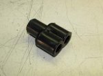
yhst-59523690850641_2267_42027783.jpg

For the rear, I mounted the "middle" (front of the bed) lights and ran the wiring along the front edge of the bed, towards the drivers side. Both wires terminate sort of near the airpack. You can see them already wrapped in their asphalt covered cloth wiring harness wrap here, along with the wiring for the various spotlights I equipped the vehicle with.

IMAG0604.jpg

Once the left and right marker light were tied together into once circuit (soldered them together into one wire), I ran the single feed wire to the rear of the truck, inside the frame, inside the factory wiring harness clamps. Of course, this feed wire is wrapped in the cloth wiring harness wrap/sheath/whatever to protect against abrasion.

When I did the rear marker lights, I was also in the process of doing reverse lights. I built a sub-harness with 2 wires (low and high beam) for the reverse lights (high beam is wired to the Peashooter/Gringeltaube switch on the transmission) and low beam is wired to a switch on the dash) and a third wire for the rear marker light. Using the aforementioned military Y connector, I also tapped into the taillight circuit on each side and ran the power feed through the harness as well.

IMAG0594.jpgIMAG0595.jpg

The power taken off the passenger taillight feeds the rear marker lights and the power taken off the drivers taillight feeds the middle marker lights. The left and right sub harnesses terminate behind the trailer connector like so:

IMAG0597.jpg

So one taillight feeds the rears and the other taillight feeds the middles. Obviously we're talking about circuit 21.

Everything is soldered, all connections are new packards and all the wiring is wrapped in Grote's cloth covering like what the factory used on the front turn signal harnesses.

Like this:

IMAG0601.jpg


Now, I'll bet somebody is going to say "You're going to overwork the headlight switch, running all those additional marker lights on the 21 circuit, all of which is fed from the headlight switch".

Several things:

1. I ran it 6 months on the original headlight switch with no problems. Even on a long trip (lights on for 8+ hours, Athens to Charlotte, non-stop) the switch didn't overheat. I ended up with a new 3 lever switch and swapped it just to be safe since my original was 25+ years old.
2. The M35A3 comes from the factory with 7 marker lights running on the 21 circuit all through the 3 lever switch.
3. When the military hooks up an M939 5 ton tractor to a 40'+ trailer covered in taillights and marker lights, all those lights are fed through the 3 lever switch (without any relays).

The finished project:

IMAG0703.jpgIMAG0615.jpgIMAG0613.jpgIMAG0706.jpg
 

tcruwithme

Member
244
19
18
Location
Eagan, MN
Good point, gimpyrobb.

Thank you for the great explanation, clinto! I'll follow your same plan for the rear marker lights. I think I'll hook up a relay and a couple diodes so that the front marker lights stay on all the time - with either low beam or high beam. My thought was to tap off low beam into a diode and then into pin #86 on a 24 volt relay, then tap off the high beam into a diode and then parallel into pin #86 on that same relay. Pin #85 on the relay goes to ground, pin #30 on the relay goes to +24 volt power, and pin #87 goes out to the front marker lights.

You might be able to do this without the relay and just use the diodes. I'm not sure how much power those marker light bulbs draw. Cheap diodes work up to about 5 watts, I think.
 

clinto

Moderator, wonderful human being & practicing Deuc
Staff member
Administrator
Super Moderator
Steel Soldiers Supporter
Supporting Vendor
12,596
1,124
113
Location
Athens, Ga.
Where did you find the wire covering?

Bought 100' of 1/4" off eBay, bought 100' of 1/2" from my local Fleet Pride store. They had to order it.

Obviously I didn't use 200' on just this project. I've been using it for any wiring project I do on both my and my customers trucks.

Here is the Grote page with the part #s of all the different sizes. You can use those part #s to search the internet for the best deal on the stuff.

http://www.grote.com/cgi-bin/goc/goc.cgi?product_number=87-1000

In the end, if you don't see it on eBay, you need to find a dealer who has Grote stuff and can order it.
 

tcruwithme

Member
244
19
18
Location
Eagan, MN
Good source for Grote non-metallic loom

Bought 100' of 1/4" off eBay, bought 100' of 1/2" from my local Fleet Pride store. They had to order it.

Obviously I didn't use 200' on just this project. I've been using it for any wiring project I do on both my and my customers trucks.

Here is the Grote page with the part #s of all the different sizes. You can use those part #s to search the internet for the best deal on the stuff.

http://www.grote.com/cgi-bin/goc/goc.cgi?product_number=87-1000

In the end, if you don't see it on eBay, you need to find a dealer who has Grote stuff and can order it.
NAPA has this stuff, but they have to order it from the manufacturer. They quoted me $52 + $7 in shipping. The best price I found was from Truck Parts Warehouse Online, and they sold it at $35.96 + $7.93 in FedEx shipping. Their phone number is (571) 292-9756 and their website is http://www.truckpartswarehouseonline.com/

Thanks again, clnto!
 
Last edited:

clinto

Moderator, wonderful human being & practicing Deuc
Staff member
Administrator
Super Moderator
Steel Soldiers Supporter
Supporting Vendor
12,596
1,124
113
Location
Athens, Ga.
NAPA has this stuff, but they have to order it from the manufacturer. They quoted me $52 + $7 in shipping. The best price I found was from Truck Parts Warehouse Online, and they sold it at $35.96 + $7.93 in FedEx shipping. Their phone number is (571) 292-9756 and their website is http://www.truckpartswarehouseonline.com/

Thanks again, clnto!
That's cheap. Much less than I paid.
 

tcruwithme

Member
244
19
18
Location
Eagan, MN
Relay wiring for dual purpose front marker light

Ok. So, I found this relay wiring diagram from a quick Google search. It looks like it would enable the front amber side marker up by the turn signal light to do both (1) always on when the turn signal is not on, and (2) flashing when the turn signal is on. I saw another thread where Bjorn from Crane Trucks put two side marker lights up by each front turn signal so that he could use one for a side-facing turn signal light. What do you think - do you think this will work?

dual_sidemarker.jpg
 
Last edited:

Prospector GM

Member
289
2
18
Location
Hesperia Ca
Ok. So after taking a second look, I found that circuit 489 taps into #21 "light switch to service tail lamp." Problem solved.

I can't figure out how to delete this thread. If a moderator wants to delete it, that's cool. Thanks for your help.
I like the thread! I am adding side marker lights to my trucks. I cut some patterns out of 1/8'' plate and welded them to the bottom four corner of the bed and to front blinker bracket. Not sure what I am going to do for the back. This information on the wiring will help me out.:)
 

clinto

Moderator, wonderful human being & practicing Deuc
Staff member
Administrator
Super Moderator
Steel Soldiers Supporter
Supporting Vendor
12,596
1,124
113
Location
Athens, Ga.

tcruwithme

Member
244
19
18
Location
Eagan, MN
So I am still thinking about how to turn the front side-facing marker lights into a dual-purpose light. I want them to stay on all the time when the light switch is in "drive," and then I want them to flash when I use the turn signal. That will give me a front side-facing turn signal light. I posted a relay wiring diagram in this thread a couple posts ago that I am confident will work. I used to do this kind of stuff all the time 20 years ago when I wired up car stereos.

Here's my situation: I need a constant light feed into the relay system for "on when in service drive." Circuit #21 (light switch to service tail lamp) would work, but that is a ways away from the front of the vehicle. My light switch is really tight in the dash. I don't want to mess around with pulling that out unless I really need to.

I could do one of two things, and I would like your opinion on which would be better.

(1) I could tap off circuit #16 "light switch to service headlamp or dimmer switch" and run that into the relay system. This wire should be easy to find, as it is right at the dimmer switch. It also looks like it is the input to the dimmer switch, and therefore is always on when the headlights are on - regardless if the low beam is on or the high beam is on. This seems to make sense, but I wanted to ask all the experts to see if there's something I am not catching here.

(2) I could run two leads off each of the low beam (circuit #18) and high beam (circuit #17) right at the headlight. Each lead would need a diode in it to isolate it from the other lead. These leads would then tie together after the diode and run into the relay system to supply the "always on when in service drive" power. These wire taps would be closest to the front marker that will get the relay system hooked up to.

Which option do you like best? Here are a couple photos of the relay system I wired up - one for each side.

20141015_161111[1].jpg 20141015_160957[1].jpg 20141015_160939[1].jpg
 
Last edited:

clinto

Moderator, wonderful human being & practicing Deuc
Staff member
Administrator
Super Moderator
Steel Soldiers Supporter
Supporting Vendor
12,596
1,124
113
Location
Athens, Ga.
You can either do an interrupter, which I like in terms of cleanliness, or you can do what cranetruck did:


http://www.steelsoldiers.com/showth...ght-kit-lights&p=106304&viewfull=1#post106304

Edited to add:

I'd probably pull power at the dimmer like you said. Since it uses an individual packard connector, you can make a sub-harness that can plug in to keep you from having the cut the original harness (I have a hangup about cutting into good harnesses).
 
Last edited:

tcruwithme

Member
244
19
18
Location
Eagan, MN
Thanks clinto,

I don't want to put two marker lights on each side. I want one marker light to do the job of both - that looks cleaner like you said and is less expensive. The relay system I wired up will do the job of an interrupter. I'm looking for input on which circuit to power the relay system with: 16 or 17 + 18 with diodes.

BTW - I bought all my marker lights from clintogf.


You can either do an interrupter, which I like in terms of cleanliness, or you can do what cranetruck did:


http://www.steelsoldiers.com/showth...ght-kit-lights&p=106304&viewfull=1#post106304
 
Last edited:

tcruwithme

Member
244
19
18
Location
Eagan, MN
Front marker lights as turn signals

Ok, so I finished installing the front marker lights on my Deuce. I got two take-off brackets from TNJ Murray that attach the marker lights to the turn signal housing just like on the 5-ton trucks. I then used the relay wiring schematic that I posted in post #11 in this same thread, and the relay system I wired up is that shown in post #15 in this same thread. The result is that my front marker lights are always on when the headlights are on, and they flash when the turn signal is activated. More specifically, the left front (driver side) flashes when the left turn signal is activated - and the right front (passenger side) stays on without flashing. Likewise, the right front (passenger side) flashes when the right turn signal is activated - and the left front (driver side) stays on without flashing.

If you want to hook up your front marker lights the same way, here are a few tips.

(1) Look at post #11 in this thread. When that schematic says "from parking lights," connect that to circuit #16. #16 is the headlight feed that goes into the dimmer switch. That means your marker lights will be on regardless if you are using low beam or high beam. You can find #16 right by the dimmer switch, from the engine side of the firewall.
(2) Also in post #11 from this thread, when it says "From turn signal," connect that to either 460 (turn indicator right) or 461 (turn indicator left). One of your relay systems will connect to 460, and the other relay system will connect to 461. You can tap into either 460 or 461 right by the turn signal light.
(3) In post #11 from this thread, when it says "to sidemarkers," hook that up just like it sounds. Run a wire from this lead to your side marker.
(4) Ground the relay system leads to the same place you have your turn signal ground.
(5) Once you have all the leads from the relay system connected, you can stuff the relays and wires into the lamp guard on the bottom side of the fender right underneath where the turn signal mounts. This lamp guard is item #15 in figure #44 in TM 9-2320-361-24P. There is plenty of space, but it is tight once you get everything in there.

Here are the parts I used to make the relay systems:
* Qty. 4 of Jameco part number 2094194, model number SARL-124DF at $3.95 each (24 volt relay)
* Qty. 2 of Jameco part number 170624, model number RSD03 at $2.49 each (relay socket)
* Qty. 2 of Jameco part number 804914, model number 1N5359BG at 10 for $2.50 (diodes, pack of 10, I only used 2)
* heat shrink tubing
* 14 gauge Packard connectors
* zip ties
* crimp connector caps (I don't like to solder)

You don't need to get the relay sockets. You can just use push connectors and hook leads directly up to the pins on the relay. I like using relay sockets, so if your relay ever goes bad, you can just pull off the relay and replace it. If you do use these sockets, cut out the small diodes that come with it that bridge two of the relay pins. Do this for both relay sockets. Also, you can pull out the wire for relay pin #87, since that relay pin is not used. Pull out the #87 lead from both relay sockets.

That's it. The result is that your front turn signal light and your side marker will flash in an alternating pattern when the turn signal is activated. In other words, your front turn signal will be on while the marker light is off. Then the marker light then flashes on while the turn signal is off. You can hear a clicking sound right by the lights - this is normal, and it comes from the relays opening and closing.

Let me know if you have any questions.
 
Last edited:

tcruwithme

Member
244
19
18
Location
Eagan, MN
Video of front marker light as turn signal

Here's a short video of my front marker lights and how they work.

http://youtu.be/1czC9y5oBKs

Here are a couple pictures of my marker lights.

20141030_132351[1].jpg 20141030_132420[1].jpg 20141030_132700[1].jpg 20141030_132729[1].jpg

Why just jazz up the Deuce with marker lights? I also installed two amber and two red marker lights on my M105A2. I only got the front amber ones hooked up today, as I ran out of Packard connectors for the rear red marker lights. That's up for next week.

20141030_132718[1].jpg
 
Last edited:
Top