• Steel Soldiers now has a few new forums, read more about it at: New Munitions Forums!

  • Microsoft MSN, Live, Hotmail, Outlook email users may not be receiving emails. We are working to resolve this issue. Please add support@steelsoldiers.com to your trusted contacts.


Isolated Ground Alternator

Brad M

New member
100
0
0
Location
Belmont NC
I just wanted to share my evening adventure with you all.

So the other day my Driver’s Side (GEN 1) Alternator threw a belt. During the replacement process, I noticed some drag on it indicating some bearing wear. I ordered a rebuild kit of eBay. I have rebuilt standard alternator before and had been reading up on working on isolated ground alternators. Today during the process, I started to remove the rear bearing but it was seized and it would not budge. Eventually i blew out the back of the case trying to remove it. So I knew I was up the creek. I remembered from here that an 84 Eldorado alternator would work. With 30 min until close, i headed to the parts store and managed to get one at the second store. I looked it over and it is almost identical. Since I was already at my whit’s end, I decided to tempt fate. I pulled the new alt apart, started comparing it to the old one, and knew I had plenty of spare parts other than casing. I figured out where the isolated ground needed to go thru and after sealing off the bearings i took a small drill bit and drilled a pilot hole. I compared my measurements and then found the size bit that fit in the old case exactly and I opened the hole up to the proper size. I then cleared the inside of the case for the isolation washers. Then I started re assembly checking at every point with a meter to make sure that the connections were only going where they were supposed to and that all the isolation grommets and washers were in the proper places. I managed to get it done in about 30 min and then put it back in my 1008. Re connected my batteries and it fired right up. So the $20 afternoon project took a bit longer and ended up at about $120 but I still have two isolated ground alternators and a spare parts. Given some time and another back half of a case and I will have a spare for the next time.
 
Last edited:

doghead

4 Star General /Moderator
Staff member
Super Moderator
Steel Soldiers Supporter
26,247
1,168
113
Location
NY
You do realize, you could have used the new alternator as it was(without converting it) in the Alt 1 location(only).

Only alt2 needs to be isolated ground.
 

1stSarge

Member
428
4
18
Location
Mount Vernon, Ohio
You do realize, you could have used the new alternator as it was(without converting it) in the Alt 1 location(only).

Only alt2 needs to be isolated ground.
I was thinking the same thing…
BUT, I wanted to say GREAT JOB Brad! I love it when people come up with solutions like this!

I feel bad because I did a Alt rebuild write up that I never posted, because I knew someone else on here was working on one. And one of the hardest things to do are the bearings. I’ll see if I can find it, (on a SD card somewhere) and I’ll show the super easy fix on how to not blow out the case.

Again great job!
 

doghead

4 Star General /Moderator
Staff member
Super Moderator
Steel Soldiers Supporter
26,247
1,168
113
Location
NY
I use an arbor press. If you use the appropriate diameter support and appropriate diameter item to press on the bearing, you can almost guarantee no damage to the case.

I think the key, even if using a hammer, would be using the appropriate diameter support and punch(diameter).
 

Brad M

New member
100
0
0
Location
Belmont NC
Yes, I know I could have but I wanted to keep it close to original. I had it on a vice close to the proper size and using a socket and extension with a hammer that was almost perfect for a drift. I am hoping my efforts eventually help others. I thought today after I got some rest and will try to put together some images and data so anyone could do the same job on their own in the future. Let me do some more pondering and get it polished and ready and I will share the knowledge.
 

Brad M

New member
100
0
0
Location
Belmont NC
This is my first write up and I am doing it from memory so read the entire write up before performing any work. There may be some errors so let me know if you find any and I will make corrections. Writer implies no warranty or chance if success since he is not the one doing work. Briefly, if you break your stuff using this I am sorry but I am not taking responsibility for it. With that said, let us continue with some background and explanation of differences.

Using TM 9-2320-289-34 we will discuss the differences in a standard 1984 27Si alternator for a Cadillac Eldorado and the isolated ground alternator of a CUCV. This write-up will require you to refer to the TM-34 for reference so take the time and download it now if you have not already.

Starting with Section 4-2 on page 262 we will see images at item 6 on page 264 showing a cross section of how the insulating washers are used on studs through the rear of the case.

On page, 271 items 7 and 8 discuss some of the components that are different from a standard 27Si. First is the “bridge to rectifier jumper wire”. Second is out of view under the rectifier bridge referred to as the “rectifier bridge fiber insulator” it is a fiber washer that fits under the rectifier bridge and prevents that side from contacting the outer casing. Finally, the “negative terminal plastic insulator” is installed in the case on the other side of the rectifier bridge. This is the area that you will find a raised section inside the case indicating where you will ultimately drill a 21/64ths hole for the negative terminal plastic insulator. You will also only use insulated screws to secure the rectifier bridge and voltage regulator and brush holder assembly.

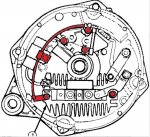
Attached is an image with the differences highlighted in red.


Think of it this way the rectifier bridge has the (+) and the (-) already as part of it and depending on the ground of the vehicle you are working with one side is already isolated from the case and directed towards a terminal thru the case. By adding the fiber washer and the insulated screws and jumper wire, you are effectively isolating both sides from the case and having each of them directed to a terminal. You have to carry this thru to the voltage regulator, which is stacked with the brush assembly also so you do not short it out.

Ok enough of the preliminary understanding now on to the instructions.

Materials required

· Old isolated ground alternator or parts from inside one
· New 27Si (1984 Eldorado) alternator … New to you works also but you may want to rebuild it if its used

Tools required

· Assortment of basic hand tools sockets etc.
· Drill with assortment of bits to include 21/64ths bit
· Ohmmeter

Old Alternator

1. Disassemble the case halves of the donor alternator and lay it so you can see the rectifier, brush assembly etc.
2. Remove the three nuts securing the stator to the rectifier and set the stator aside.(it may be stuck to the case half)
3. Remove the three insulating screws securing the voltage regulator, brush holder, and save them for use in the new alternator.
4. Remove the remaining screws holding the jumper wire and set it and the insulating screw used to connect it to the rectifier aside for use in the new alternator.
5. Remove the remaining screws that are on the inside holding the jumper plates to the rectifier so other than the (-) stud it is free (plates can be pushed aside rather than removed as long as the rectifier can be removed in a future step)
6. If not already done remove diode trio
7. Remove the nut holding the (-) stud thru the case
8. Gently pull rectifier from case with (-) stud paying close attention to the washer and plastic insulator stack
9. Remove the fiber washer from where the rectifier was positioned

New Alternator (You are voiding any warranty by opening a new alternator so do it at your own risk!)

10. Using toothpick or paperclip secure brushes of new alternator so they do not fall out when the case halves are separated.
11. Separate case halves of new alternator (separate piles of parts from new and old makes life easier later so keep that in mind)
12. As with you did with the old remove the stator of the new alternator and set aside.
13. If you did not have the brushes pinned properly in step 10 then repack them and secure with a toothpick or paperclip
14. Remove the diode trio from the new alternator. Unsecure all items from the rectifier and remove it from the case.
15. Take tape and cover the needle bearing in the rear of the case making sure it is covered so shavings and filings made in future steps do not get in it.
16. Locate the raised boss in the back of the case where the (-) stud should go thru the case and compare it to the old case.
17. Drill a small pilot hole from inside the case to outside centering it as the old case had it.
18. Make absolutely sure your pilot hole is where it should be and move if needed (you can’t undo the final hole so now is your chance to make corrections)
19. Once satisfied with your pilot hole use a 21/64ths size drill bit and chase your pilot hole to enlarge it to 21/64ths.
20. Check the inside of your case near the new hole and on the other end of where the rectifier will sit for additional positioning bosses in the case that could come in contact with the rectifier and or impede the seating of the fiber washer that will insulate the other side of the rectifier.
21. Clearance the case of the afore mentioned bosses with a dremmel tool or as I did use a very small drill bit to weaken them and remove them with pliers. (Do not drill to the outside when weakening the bosses with a small drill bit)
22. Check for a smooth flush finish to the removed boss area by placing washer in area and checking for any raised area and remove more material as needed.
23. Clean case inside of any shavings or filings (do a thorough job as you don’t want this getting into the works later)
24. Place (-) stud into slot in rectifier
25. Place plastic (-) stud grommet in case and set fiber washer over its threaded mounting hole
26. Lower rectifier with (-) stud into case half until seated and add insulating washer stack and nut to (-) stud
27. Placing one end thru tab on jumper wire secure other end of rectifier with an insulated screw making sure to get it thru the fiber washer under the rectifier.
28. Check case and rectifier with ohmmeter. Makes sure that case is not connected to (-) stud. If it is check that, the jumper wire is not laying inside the case completing the circuit. If it is, correct and retest. Of not check for other issues before proceeding.
29. Once insulated continue by removing cap mounting screw and placing center support of jumper wire on screw and re-securing cap.
30. Re connect cap to (+) side of rectifier with standard screw
31. Remove standard screw from brush holder /voltage regulator stack on opposite side of resistor from the side connected to the diode trio. Replace with insulated screw that is fed thru the end of the jumper wire. (refer to attached image for visable items)
32. Replace other screws as needed in brush holder/ regulator stack with insulated screws as needed.
33. Re attach diode trio and jumpers to (+) stud and (R) stud
34. Check all studs to case making sure nothing is shorted to the case using ohm meter
35. Replace stator and secure with nuts
36. Remove tape covering needle bearing
37. Put case halves back together and check with ohmmeter again.
38. Pull paperclip or toothpick allowing brushes to contact commutate rings again.

Congratulations, you have just taken a standard 27Si and made it an isolated ground unit. If you already had the parts, you could begin at step 10 and not disassemble the old unit but I recommend it for the positioning of the (-) stud. Once you do it a few times, you will not need to refer to an old case half. This took me about an hour to do with minimal tools but take your time and do it right the first time.
 

Attachments

Last edited:

Brad M

New member
100
0
0
Location
Belmont NC
Yes, I know I could have but I wanted to keep it close to original. I had it on a vice close to the proper size and using a socket and extension with a hammer that was almost perfect for a drift. I am hoping my efforts eventually help others. I thought today after I got some rest and will try to put together some images and data so anyone could do the same job on their own in the future. Let me do some more pondering and get it polished and ready and I will share the knowledge.
Well I hope everyone likes it, it's my first shot at it so let me know if I made any errors and I'll fix them.
 

ThroopJ

New member
3
0
0
Location
Fayetteville/Arkansas
So, what is the possiblity of sourcing the individual parts required to convert a standard alternator into an isolated ground alternator? Reason I am asking is because I recently purchased a 1986 M1009 and the previous owner did not have the original alternators and both are the driver side alternators.

I am trying to find out how to buy a kit that would allow me to convert the alternator into the isolated ground alternator. Otherwise, I am obviously going to have to break down and buy the correct $200 reman.
 

cucvrus

Well-known member
11,271
9,596
113
Location
Jonestown Pennsylvania
The alternators both need to be isolated ground. The alternators on a stock 24 volt CUCV are the same on either side. No difference. So you will need 2 isolated ground alternators. Most rebuilders can handle this set up for a few dollars I would think. Report back. Welcome to the hobby. Don't do everything everyone tells you to do.
 

ThroopJ

New member
3
0
0
Location
Fayetteville/Arkansas
Thanks. I am enjoying even chasing this demon. So they're both DR alternators 7157s... I know that both were swappable with isolated grounds. The condensor/capacitor is for noise suppression and is not necessarily needed. I have aground fault when I go to wire up my (-) terminal on the front battery. I looked at another owners' wiring set which is correct; I wired accordingly to the CUCV electric diagram...

But upon further inspection, I realized the center bolt hole is not the negative terminal used for the re/white wire and the supressor wire... I didn't intend to discuss my wiring problem. I just know if I want to make the 24v system work, I need to have the right crap in GEN 2.
 

doghead

4 Star General /Moderator
Staff member
Super Moderator
Steel Soldiers Supporter
26,247
1,168
113
Location
NY
The alternators both need to be isolated ground.
You do not need the driver side alternator to be an original isolated ground(it gets grounded with a short wire).

I think you already understand this from your posts.
 

cucvrus

Well-known member
11,271
9,596
113
Location
Jonestown Pennsylvania
gg15-650x433Marlboro's.jpg
You do not need the driver side alternator to be an original isolated ground(it gets grounded with a short wire).

I think you already understand this from your posts.
OK. Let me correct my post. If you have 2 spare alternators and you want to be prepared at all times. Make sure you have 2 that have isolated grounds. That way they will be able to be used in any position/side 1 or 2 / R/L. I knew what I meant but did not write what I was thinking. Make any sense? I have all my alternators rebuilt at the shop so they are isolated grounds. It works well that way. Have a great day. 420
 

ThroopJ

New member
3
0
0
Location
Fayetteville/Arkansas
So I'm still not getting my question answered. I am asking if anyone has the knowledge OR knows if you can source the required parts that adapt a "regular" alternator into an isolated ground alternator. I have purchased a CUCV that has 2 non-isolated/ Gen 1/ Driver's Side remanufactured alternators. I want to see if I can modify (the currently un-wired) Gen 2 alternator that has no internal parts or isolated ground post.

Thanks!
 
Top
AdBlock Detected

We get it, advertisements are annoying!

Sure, ad-blocking software does a great job at blocking ads, but it also blocks useful features of our website like our supporting vendors. Their ads help keep Steel Soldiers going. Please consider disabling your ad blockers for the site. Thanks!

I've Disabled AdBlock
No Thanks