Note, this post ended up way longer than I anticipated and I will update some images tomorrow as I think others may also.
Also, Without diving to far in. Im new to forums, but if you dive in searching for info. and see multiple posts from a user, double check the items in their signature for links. very helpful info for the common items. Such easy access I havent thanked them yet....
Its Ideal to get a feel for the year that your rig was last used. This can be by notes on the filters/ date codes on batts or tires. Main tool for diagnosis is a digital multi meter DMM
New to the forum and trucks. The info and support is great. I wanted to give a run down on my findings for a non charging rig. Your rig wont like much of anything if this system isnt operating correctly, I.E. Trans issues, Lights, and I think CTIS. There are many posts about all the related items, from truck year-equipment-use-and everything from the battery to the belts. I want to touch on a few things i picked up from reading the posts,TM's and general observations. Hoping that this can help someone in the future along with the other posts. To start, I have a general knowledge of trouble shooting, but plan on laying it out in a simple way so it will help all on any level. Of coarse there are a few things I learned the hard way and want to share a few tips that I found useful and maybe others can supply some also.
Ive typically referred to the main Voltage as the 12V in the auto industry. Most of what i have seen here is that it is referred to the Desired output voltage of 14V-28V
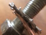
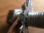
DO YOU HAVE A BATTERY TERMINAL DIAGRAM?
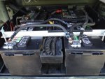
First, Batteries. Regardless of what direction you go with style or brand, If you dont know the history and are having trouble with them it may be time to start there. A standard car/ truck battery is basic in the batt/alt system. From reading most peoples posts , and what they are up against is wanting to run a rig on the Batts that were in the rig when they got it. This system comprised as four batteries factory can be modified in many ways. Operating with a 12V and 24V system with multiple batteries brings a large requirement for them to work together. From my understanding, Batteries can have a number of issues. This can vary from style- AGM, Lead acid, AKA low maintenance- No maintenance (maintenance free) Charge history, odd ball batteries thrown in, over charge or constant running low and overworking. The next stop would be the battery cables and connections.
I found my truck (M1090 Runner with jump) with the 6T AGM's from what looked like the 05 era. When it was on the trailer I had everything hooked up trying to fire it up to drive it off. Two things- one the trans doesnt like having low voltage and it didnt want to crank with my arsenal of valtage hooked up. Mostly because of lack of working on the rigs, trying to be quick. Finally hooked up an air line to undo the brakes and tow off the trailer. Then found the Batt cover in the bed later that day") I did have two slave batts,two jump boxes and a charger on it... Just doing my thing with no luck.
I did have two slave batts,two jump boxes and a charger on it... Just doing my thing with no luck.
Batt style. I decided to run the factory setup (stock as a rock) as I knew this would allow me to get where i wanted to be asap. After looking at some of the forums and posts the arrangements of styles can very. 2) 8D's. 4-6 Group31's. 4) 6T's like factory. I used the factory setup and retained the hold down and cables ( all in good condition). If your terminals and cables are shot ,might lean you in the direction of for different batt setups. BTW if still in place, the thing in the center of the hold down (curly que wire with a wand with red LED is for testing lead acid batteries).
Advanced testing of old batteries will tell you what you need if you are trying to keep them in the equation. Snap on testers test each asspect of the battery and will give a health report.
Batteries need to have good health. If you know the history it will give you a piece of mind and will answer a lot of questions. Clean terminals and good ground at the box
The variations around the box to my understanding is related to year/ series of rig. On the right side it can have a simple plug for a slave cable to jump power to rigs. From my reading- Some will have a larger box with a battery disconnect switch on the bottom and disconnects inside?
Next up is the Junction style under the spare tire. Depending on the rig this can be a Polarity Protection Device, Brand (SURE POWER PROTECTION DEVICE) only has the 12V and 24V wires in and 12V and 24V wires out. On the output side it should reflect a Slight drop (roughly .7V) This terminal feeds to the cab main power distribution panel. PDP. Note that the PDP has a specific layout with 12V and 24V Relays and Circuit breakers. 24V relays have 5 terminals and 12V have 4? Double check the relays are appropriate for the placement. Ive seen many images where lots of them are missing on rigs. This unit has diods in it to protect against hooking up the DC voltage incorrectly.
The other style is the LBCD - (load battery control device) Brand (NEIHOFF) It has the same inputs and outputs that the PPD, but has a harness (five wires) that ties into it to manage the charge control from the Alt. based on battery voltages and charge state. It also has An LED to let say what stat it is in. (see the Neihoff links for info later)
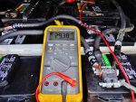
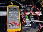
From my readings, many have found issues here with a loose terminal, broken stud when trying to loosen the nut. Testing the voltage on the input and output side will let you know the state of the connections. and output. Then checking the voltage at the PDP, and at the ALT for both 14V and 28V.
PDP. From what ive seen the K11 is the exciter relay tied into the oil pressure signal to the ALT to rectify/energize the charging state?
NIehoff has great diag. flow charts. Once you get the numbers from your ALT/REG and what type of box under the spare tire.
At the Alt. Factory style 100Amp. You will find that you may have a variation of ALts. Neihoff N1506 with my understanding is the N3030 regulator atttached (NO LEDS) The other is the N1509 (with LEDS) which i believe is a later model that can be on earlier rigs, mine being 94 with a PPD rather that the LBCD.
ON the regulator you will find the front terminal (closet to the radiator front of engine) is the 28V signal to tell the ALt to energize (start charging) This signal voltage is sent after the oil pressure signal is satisfied at 15PSI? Main function is to allow the engine start function to complete and RPM to satisfy before full draw of the Alt can be ignited to cause a strain. AKA excessive noise belt slipping.
The key is to remove the front terminal on the Voltage Regulator and test the voltage with the engine running at the wire that feeds to the regulator. DO you have 24V? This is the Excite, Exciter wire that is mentioned so much. The wire can have many issues to why it doesnt provide the voltage to Ignite(rectify) the ALT. Some will say its designed to operate a certain way so fix it piece by piece. I can Agree with that to an extent. I feel most of our use of these trucks will be under stated for the life of the consumable parts. The Key that is mentioned so many times is an excite wire from the fuel solenoid positive. It is a keyed on signal that will tell (excite/start) the ALT to charge. Not a factory solution, but in terms of most uses will fill the needs.
If you have a runner and dont have 24V to the front terminal to the REG. it is a simple test ti excite the ALT. Easiest is the 24V from the lug at the ALT. Jump to the front lug of the REG to tell it to fire up the ALT charge circuit. Otherwise you can get 24V from the PDP, PPD, or straight form the 24v Batt signal to try to energize the charge function.
NOTICE- THE WIRE CONFIGURATION OF THE VOLT/REG.... 5 WIRE FOR EARLIER MODELS 3030. 6 WIRES ON 3207. THIS WILL BE IMPORTANT IF YOU TEST OUT FOR ALT/REG.
Alternator, Niehoff is the brand. 100amp factory. seen some 200amp from Hummers installed but requires different PDP etc.as they are rated at the factory 100amp.
Once you know your model you can search the Flow chart for diag. from Neihoff. Ive searched the site and started down a link to find it was the wrong ALT or REG. Get the numbers from the equipment on your rig.
From Niehoff's flow chart. When you get the flow chart for your model ALT. It is critical to understand the terminology of each item. Based on the images, B-....so Negative. Then B+ for 14V and 28V. The main lugs. (Note the washers between the + lugs are fusible links. Havent found much out other than that they are there.)
I started on this flow chart and had to talk a day to get in the groove.(most likely due to sitting around to long)
I found the term Connector harness/ alt. a little confusing as they dont give a description beyond that of images. One main ket is when theu mention to jump from the Alt to the B- they are talking about the ground on the alt to the chassis. Not the B- terminal of the reg., The main things to realize is in that flow chart they are talking about . There are three components when the alt to reg harness is disconnected. the B+14V ---B+28V---B- as in negative. The connection between the ALT and Reg had its own designation and purpose of the voltages. They are labeled A-E on terminals but have designations of the different positive voltages and ground. Its interesting how they list them. I messed up on one the first. It is key to recognize the diff between B- on the harness (Between the alt and reg) and B- on the ALt. A on the harness to B- AKA Ground will energize the fields creating a magnetism on the center shaft of the ALT. when you do this jump you can hod a piece of metal by the center shaft and feel it pull the it in as a magnet. Pics will help spell this out.
When testing the harness alt to reg With good batts you can do some major welding/frying of the leads from the alt. I found a wire with a butt connector was best sutied to protect shorts between lugs. ( I shorted one out and had to clean it up. wasnt pretty, much different form 12V
The main part is getting down to the main issue. So often do we find that a connection or a simple item is the Hello moment. The understanding of these ALTs being brush less and pretty stout should allow some confidence in the surrounding items.
I hope this helps. I will add images for the descriptions above, WOuld love others input as ive just dove in ready to make something happen.
Im after a N3207 Regulator if you have one
Cheers
Also, Without diving to far in. Im new to forums, but if you dive in searching for info. and see multiple posts from a user, double check the items in their signature for links. very helpful info for the common items. Such easy access I havent thanked them yet....
Its Ideal to get a feel for the year that your rig was last used. This can be by notes on the filters/ date codes on batts or tires. Main tool for diagnosis is a digital multi meter DMM
New to the forum and trucks. The info and support is great. I wanted to give a run down on my findings for a non charging rig. Your rig wont like much of anything if this system isnt operating correctly, I.E. Trans issues, Lights, and I think CTIS. There are many posts about all the related items, from truck year-equipment-use-and everything from the battery to the belts. I want to touch on a few things i picked up from reading the posts,TM's and general observations. Hoping that this can help someone in the future along with the other posts. To start, I have a general knowledge of trouble shooting, but plan on laying it out in a simple way so it will help all on any level. Of coarse there are a few things I learned the hard way and want to share a few tips that I found useful and maybe others can supply some also.
Ive typically referred to the main Voltage as the 12V in the auto industry. Most of what i have seen here is that it is referred to the Desired output voltage of 14V-28V
DO YOU HAVE A BATTERY TERMINAL DIAGRAM?
First, Batteries. Regardless of what direction you go with style or brand, If you dont know the history and are having trouble with them it may be time to start there. A standard car/ truck battery is basic in the batt/alt system. From reading most peoples posts , and what they are up against is wanting to run a rig on the Batts that were in the rig when they got it. This system comprised as four batteries factory can be modified in many ways. Operating with a 12V and 24V system with multiple batteries brings a large requirement for them to work together. From my understanding, Batteries can have a number of issues. This can vary from style- AGM, Lead acid, AKA low maintenance- No maintenance (maintenance free) Charge history, odd ball batteries thrown in, over charge or constant running low and overworking. The next stop would be the battery cables and connections.
I found my truck (M1090 Runner with jump) with the 6T AGM's from what looked like the 05 era. When it was on the trailer I had everything hooked up trying to fire it up to drive it off. Two things- one the trans doesnt like having low voltage and it didnt want to crank with my arsenal of valtage hooked up. Mostly because of lack of working on the rigs, trying to be quick. Finally hooked up an air line to undo the brakes and tow off the trailer. Then found the Batt cover in the bed later that day
I did have two slave batts,two jump boxes and a charger on it... Just doing my thing with no luck.Batt style. I decided to run the factory setup (stock as a rock) as I knew this would allow me to get where i wanted to be asap. After looking at some of the forums and posts the arrangements of styles can very. 2) 8D's. 4-6 Group31's. 4) 6T's like factory. I used the factory setup and retained the hold down and cables ( all in good condition). If your terminals and cables are shot ,might lean you in the direction of for different batt setups. BTW if still in place, the thing in the center of the hold down (curly que wire with a wand with red LED is for testing lead acid batteries).
Advanced testing of old batteries will tell you what you need if you are trying to keep them in the equation. Snap on testers test each asspect of the battery and will give a health report.
Batteries need to have good health. If you know the history it will give you a piece of mind and will answer a lot of questions. Clean terminals and good ground at the box
The variations around the box to my understanding is related to year/ series of rig. On the right side it can have a simple plug for a slave cable to jump power to rigs. From my reading- Some will have a larger box with a battery disconnect switch on the bottom and disconnects inside?
Next up is the Junction style under the spare tire. Depending on the rig this can be a Polarity Protection Device, Brand (SURE POWER PROTECTION DEVICE) only has the 12V and 24V wires in and 12V and 24V wires out. On the output side it should reflect a Slight drop (roughly .7V) This terminal feeds to the cab main power distribution panel. PDP. Note that the PDP has a specific layout with 12V and 24V Relays and Circuit breakers. 24V relays have 5 terminals and 12V have 4? Double check the relays are appropriate for the placement. Ive seen many images where lots of them are missing on rigs. This unit has diods in it to protect against hooking up the DC voltage incorrectly.
The other style is the LBCD - (load battery control device) Brand (NEIHOFF) It has the same inputs and outputs that the PPD, but has a harness (five wires) that ties into it to manage the charge control from the Alt. based on battery voltages and charge state. It also has An LED to let say what stat it is in. (see the Neihoff links for info later)
From my readings, many have found issues here with a loose terminal, broken stud when trying to loosen the nut. Testing the voltage on the input and output side will let you know the state of the connections. and output. Then checking the voltage at the PDP, and at the ALT for both 14V and 28V.
PDP. From what ive seen the K11 is the exciter relay tied into the oil pressure signal to the ALT to rectify/energize the charging state?
NIehoff has great diag. flow charts. Once you get the numbers from your ALT/REG and what type of box under the spare tire.
At the Alt. Factory style 100Amp. You will find that you may have a variation of ALts. Neihoff N1506 with my understanding is the N3030 regulator atttached (NO LEDS) The other is the N1509 (with LEDS) which i believe is a later model that can be on earlier rigs, mine being 94 with a PPD rather that the LBCD.
ON the regulator you will find the front terminal (closet to the radiator front of engine) is the 28V signal to tell the ALt to energize (start charging) This signal voltage is sent after the oil pressure signal is satisfied at 15PSI? Main function is to allow the engine start function to complete and RPM to satisfy before full draw of the Alt can be ignited to cause a strain. AKA excessive noise belt slipping.
The key is to remove the front terminal on the Voltage Regulator and test the voltage with the engine running at the wire that feeds to the regulator. DO you have 24V? This is the Excite, Exciter wire that is mentioned so much. The wire can have many issues to why it doesnt provide the voltage to Ignite(rectify) the ALT. Some will say its designed to operate a certain way so fix it piece by piece. I can Agree with that to an extent. I feel most of our use of these trucks will be under stated for the life of the consumable parts. The Key that is mentioned so many times is an excite wire from the fuel solenoid positive. It is a keyed on signal that will tell (excite/start) the ALT to charge. Not a factory solution, but in terms of most uses will fill the needs.
If you have a runner and dont have 24V to the front terminal to the REG. it is a simple test ti excite the ALT. Easiest is the 24V from the lug at the ALT. Jump to the front lug of the REG to tell it to fire up the ALT charge circuit. Otherwise you can get 24V from the PDP, PPD, or straight form the 24v Batt signal to try to energize the charge function.
NOTICE- THE WIRE CONFIGURATION OF THE VOLT/REG.... 5 WIRE FOR EARLIER MODELS 3030. 6 WIRES ON 3207. THIS WILL BE IMPORTANT IF YOU TEST OUT FOR ALT/REG.
Alternator, Niehoff is the brand. 100amp factory. seen some 200amp from Hummers installed but requires different PDP etc.as they are rated at the factory 100amp.
Once you know your model you can search the Flow chart for diag. from Neihoff. Ive searched the site and started down a link to find it was the wrong ALT or REG. Get the numbers from the equipment on your rig.
From Niehoff's flow chart. When you get the flow chart for your model ALT. It is critical to understand the terminology of each item. Based on the images, B-....so Negative. Then B+ for 14V and 28V. The main lugs. (Note the washers between the + lugs are fusible links. Havent found much out other than that they are there.)
I started on this flow chart and had to talk a day to get in the groove.(most likely due to sitting around to long)
I found the term Connector harness/ alt. a little confusing as they dont give a description beyond that of images. One main ket is when theu mention to jump from the Alt to the B- they are talking about the ground on the alt to the chassis. Not the B- terminal of the reg., The main things to realize is in that flow chart they are talking about . There are three components when the alt to reg harness is disconnected. the B+14V ---B+28V---B- as in negative. The connection between the ALT and Reg had its own designation and purpose of the voltages. They are labeled A-E on terminals but have designations of the different positive voltages and ground. Its interesting how they list them. I messed up on one the first. It is key to recognize the diff between B- on the harness (Between the alt and reg) and B- on the ALt. A on the harness to B- AKA Ground will energize the fields creating a magnetism on the center shaft of the ALT. when you do this jump you can hod a piece of metal by the center shaft and feel it pull the it in as a magnet. Pics will help spell this out.
When testing the harness alt to reg With good batts you can do some major welding/frying of the leads from the alt. I found a wire with a butt connector was best sutied to protect shorts between lugs. ( I shorted one out and had to clean it up. wasnt pretty, much different form 12V
The main part is getting down to the main issue. So often do we find that a connection or a simple item is the Hello moment. The understanding of these ALTs being brush less and pretty stout should allow some confidence in the surrounding items.
I hope this helps. I will add images for the descriptions above, WOuld love others input as ive just dove in ready to make something happen.
Im after a N3207 Regulator if you have one
Cheers