• Steel Soldiers now has a few new forums, read more about it at: New Munitions Forums!

  • Microsoft MSN, Live, Hotmail, Outlook email users may not be receiving emails. We are working to resolve this issue. Please add support@steelsoldiers.com to your trusted contacts.


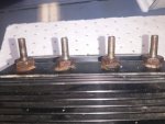
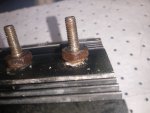
LBCD replacement due to loose studs. CARNAGE!!

GeneralDisorder

Well-known member
Steel Soldiers Supporter
1,467
4,097
113
Location
Portland, OR
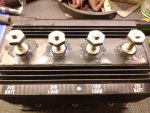
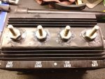
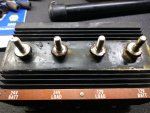
When addressing loose and corroded connections at the LBCD I noted that several studs were loose in the housing. After confirming with several members that this was a clear indication of failure (the unit is no longer sealed against moisture at the very least), I procured and installed a replacement - which seems in OK condition - no corrosion evident anywhere that I can see, and all studs tight in their epoxy. No discoloration around the back side where it's potted with silica sand and silicone. Build date of 2011.

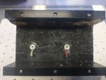
I used Dow Molykote 111 on the studs and wire terminals:
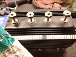
IMG_20220102_103538339.jpg
IMG_20220102_103820657.jpg
IMG_20220102_104053285.jpg

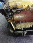
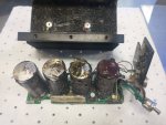
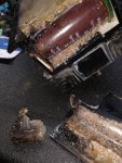
I installed and tested the truck prior to disassembly of the old unit.... which I guess was doing..... something?!? Though I'm not sure what use it could have been:
IMG_20220102_122448753.jpg
IMG_20220102_122817210.jpg
IMG_20220102_122921436.jpg
IMG_20220102_123318_01.jpg

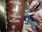
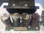
I need to sit down and attempt a more in-depth autopsy and actually test these caps but from first looks it appears all the capacitors have failed and leaked inside the case. The silicone at the bottom edge was already loose from the housing and the corner pried away easily.

Note that none of that is visible without removing the unit from the truck. The only thing I could see with it installed was that the studs were loose in the epoxy.

The serial number of my original 2008 box was in the 2x,xxx range, while the 2011 unit was 60,xxx range.

I now wonder what the use-by date of these is and if anyone else has evidence of capacitor leakage. I'm also curious what symptoms we are likely to see with this failure mode. My 14v side was tending to fluctuate quite a bit especially immediately after cold start - the gauge would swing from around 13 up to 14 back and forth a bit. After driving for a while it would settle out around 14v and seemed to hold steady. After starting it up with the new box it seemed to fluctuate less, though there was still a bit of a swing - maybe half a volt this time. After what seemed like a shorter time the voltage's were both steady on 28v and 14v. But this wasn't a totally cold start since I had to move the truck to lower the spare for access to the LBCD.

As I understand it, all the A1 trucks have this unit. Mine specifically is an A1R with the 260 amp alternator. For reference.

Rick
 

NDT

Well-known member
Steel Soldiers Supporter
10,163
5,839
113
Location
Camp Wood/LC, TX
I thought these had diodes inside? Someone explain what capacitors are doing in there? Sorry CE Niehoff, this thing is not one of your better ideas.
 

Ronmar

Well-known member
3,268
6,610
113
Location
Port angeles wa
They may have built a noise suppression filter into the device to help cut down on the trucks(alternator) electromagnetic signature. They put filters on the wiper, washer and heater motors for this reason… The LBCD also contains the alternator load monitor circuitry, so would expect you to find a circuit board in there also, probably near the cannon plug and LED at the other end…
 

GeneralDisorder

Well-known member
Steel Soldiers Supporter
1,467
4,097
113
Location
Portland, OR
These are BIG caps. Near as I can tell they have two 120,000 μF @ 16v caps on the 12v side..... I haven't dug far enough into it to see the rating on the top two and I'm just guessing they might be different because up there is the 28v side. Purely a guess though.

And yes - I'm guessing to cut down on voltage spikes for the load circuitry. Caps are mostly used to filter out "noise" in DC systems. Such as the ripple current seen after using a bridge rectifier inside an alternator. Most alternators have their filter caps built into their rectifier which is typically inside the alt..... but then on *most* modern applications the voltage regulator is also built into the alt so not sure of the Niehoff brushless design as regards the location of the rectifier and smoothing caps. These may also just be in addition to the rectifier smoothing caps and used to provide a cleaner voltage....

The LBCD is also capable of "switching off" the batteries - that's the huge battery disconnect box on the side of the battery tray that has the big disconnect on the bottom. That houses the battery disconnect relays..... the caps may be present to smooth the disconnect spike if the LBCD decides to throw the relay when the alt is under full (too much) load.

All guesses......

IMG_20220102_123753101.jpg

Rick
 
Last edited:

Mullaney

Well-known member
Steel Soldiers Supporter
Supporting Vendor
7,357
19,060
113
Location
Charlotte NC
These are BIG caps. Near as I can tell they have two 120,000 μF @ 16v caps on the 12v side..... I haven't dug far enough into it to see the rating on the top two and I'm just guessing they might be different because up there is the 28v side. Purely a guess though.

And yes - I'm guessing to cut down on voltage spikes for the load circuitry. Caps are mostly used to filter out "noise" in DC systems. Such as the ripple current seen after using a bridge rectifier inside an alternator. Most alternators have their filter caps built into their rectifier which is typically inside the alt..... but then on *most* modern applications the voltage regulator is also built into the alt so not sure of the Niehoff brushless design as regards the location of the rectifier and smoothing caps. These may also just be in addition to the rectifier smoothing caps and used to provide a cleaner voltage....

The LBCD is also capable of "switching off" the batteries - that's the huge battery disconnect box on the side of the battery tray that has the big disconnect on the bottom. That houses the battery disconnect relays..... the caps may be present to smooth the disconnect spike if the LBCD decides to throw the relay when the alt is under full (too much) load.

All guesses......

View attachment 854953

Rick
.
Yeah, those caps would definitely knock the fuzz out of your bellybutton if you went poking around in there bare handed!
 

coachgeo

Well-known member
4,968
3,340
113
Location
North of Cincy OH
would caps also be used in the "load balance" design of the LBCD's role. As in does this unit also take on role as a "battery balancer" ? to avoid A0 and early A1 trucks issues with unbalanced batteries?
 

Ronmar

Well-known member
3,268
6,610
113
Location
Port angeles wa
would caps also be used in the "load balance" design of the LBCD's role. As in does this unit also take on role as a "battery balancer" ? to avoid A0 and early A1 trucks issues with unbalanced batteries?
No the balance function is provided by the regulator on the alternator...

There is only really one reason to have caps like that…
 
Last edited:

Wingnut13

Well-known member
Steel Soldiers Supporter
232
556
93
Location
Strafford, NH
Wow, I thought there would be some sort of magic in that box because of all the cooling fins. Some sort of load balancer…….or something. I don’t see anything special other than capacitors that would dampen voltage spikes.
 

GeneralDisorder

Well-known member
Steel Soldiers Supporter
1,467
4,097
113
Location
Portland, OR
Wow, I thought there would be some sort of magic in that box because of all the cooling fins. Some sort of load balancer…….or something. I don’t see anything special other than capacitors that would dampen voltage spikes.
There are big honkin diodes set into the epoxy with the main studs such that it protects against reverse polarity.

There is big caps to suck up any massive voltage spikes such as when the LBCD trips the battery disconnect.

And there is rudimentary circuitry to monitor how much load the batteries are putting on the alternator so the LBCD can determine when/if to trip the battery disconnect.

There's no brain with CANBUS in this one like there is on the voltage regulator, etc. It's mostly dumb passives.
 

NDT

Well-known member
Steel Soldiers Supporter
10,163
5,839
113
Location
Camp Wood/LC, TX
There are big honkin diodes set into the epoxy with the main studs such that it protects against reverse polarity.

There is big caps to suck up any massive voltage spikes such as when the LBCD trips the battery disconnect.

And there is rudimentary circuitry to monitor how much load the batteries are putting on the alternator so the LBCD can determine when/if to trip the battery disconnect.

There's no brain with CANBUS in this one like there is on the voltage regulator, etc. It's mostly dumb passives.
The battery disconnect is internal to the LBCD or the solenoid pair over by the batteries?
 

GeneralDisorder

Well-known member
Steel Soldiers Supporter
1,467
4,097
113
Location
Portland, OR
Oh, totally missed that there were diodes there….
Yeah you can't see them because they are set in the epoxy - but I can test between the batt and load terminals and they are definitely present. There's about a 0.4v drop in forward bias so I'm guessing a Schottky Diode is being used. I don't know the size of them but I would assume they are substantial given that typical automotive testing of reverse polarity is around -150v and that's for a 12v system.....
 

Ronmar

Well-known member
3,268
6,610
113
Location
Port angeles wa
Yea the heat syncs are for the diodes, All the electrical power used by the truck, other than to crank the starter motor passes thru those diodes…

The circuitry monitors the duty cycle that the regulator pulses the alternator field via that F- or AC terminal on the regulator. When it sees a certain duty cycle it determines the alternator is overloaded and opens the battery disconnect solenoids over at the battery box.

It also has an output up to the idiot light panel to let you know of alternator trouble. It may monitor output voltage to determine this…

The disconnect relays over at the battery box send a signal to the idiot panel to tell you when the batteries are disconnected…
 

NDT

Well-known member
Steel Soldiers Supporter
10,163
5,839
113
Location
Camp Wood/LC, TX
Help me understand this folks: Alternators have been able to protect themselves from overloads since the first Delco back in the 60's. Why all of a sudden do these Niehoffs need this external device with all the "limp home" isolation silliness? No other vehicle has this thing.
 

Wingnut13

Well-known member
Steel Soldiers Supporter
232
556
93
Location
Strafford, NH
If I HAD to take a WAG at it I’d say it’s probably for EMP hardening? Though I hadn’t seen anything that would help the 3126 / C7 computer out. Seems there are some people here that would know about it, if that’s the case at all.
 

Ronmar

Well-known member
3,268
6,610
113
Location
Port angeles wa
Help me understand this folks: Alternators have been able to protect themselves from overloads since the first Delco back in the 60's. Why all of a sudden do these Niehoffs need this external device with all the "limp home" isolation silliness? No other vehicle has this thing.
Most alternators don’t protect themselves from overload, try arc welding or charging lithium batteries directly with one:) they do tend to self derate with temp increase, and I believe these alts do so as well, but that is partly to accommodate differences in charging hot lead acid batteries. overloaded alts will overheat and cook.

The reason most alternators don’t have any problems keeping their batteries charged and live a long life, is that they are properly sized for the loads and battery bank that they are feeding. Basically, even worst case they are never running at 100%. I did the numbers on my Toyota a while back and I think worst case it is only ever about 60-70% loaded.

A hundred amp alt spread across 12 and 24V feeding a 240AH bank is very improperly sized, especially on the 12v side on these trucks. The kind of improper that class action lawsuits and mass recalls are made of… Its not ark welding mismatched, but it is long hours loaded above 100% load trying to charge the batteries mismatched. That is if they get run enough hours to even charge the battery fully…

The LBCD was their bandaid, but I think the shift to AGM batteries(nearly twice the charging load) made the problem too big to hide, so they finally put a 260A alt on the A1R… With that large of an alt, the LBCD pretty much becomes unnecessary, but it will be kinder on the alt if the battery bank is really neglected/fails…
 
Last edited:

Ronmar

Well-known member
3,268
6,610
113
Location
Port angeles wa
The running load of the truck with everything on is perhaps 30A@14V or about 420W, And maybe 20A@28V for another 560W or 980W total.

With dead batteries and everything turned on, the alt will probably be delivering it’s 60A max load@14v and the remaining 40A@28V. Thats 1960W. When the LBCD disconnects the batteries at max load, best case those caps have to absorb the difference, or nearly a killowatt for as long as it takes the regulator to sense the over-voltage, limit the field current and for the field to collapse and reduce output. Worst case nothing is turned on but the batteries are still driving the alt to full load and those caps have to catch nearly all that 1960W output:)
 
Top
AdBlock Detected

We get it, advertisements are annoying!

Sure, ad-blocking software does a great job at blocking ads, but it also blocks useful features of our website like our supporting vendors. Their ads help keep Steel Soldiers going. Please consider disabling your ad blockers for the site. Thanks!

I've Disabled AdBlock
No Thanks