• Steel Soldiers now has a few new forums, read more about it at: New Munitions Forums!

  • Microsoft MSN, Live, Hotmail, Outlook email users may not be receiving emails. We are working to resolve this issue. Please add support@steelsoldiers.com to your trusted contacts.


LMTV '04 M1078A1 starting issues

Ronmar

Well-known member
3,269
6,611
113
Location
Port angeles wa
I think it is looking for the interactions seen in the series string. IE: if it adjusts the 28V it is expecting a comparable movement in the 14v side and vis-versa. or perhaps for a given amount of 28v field drive to reach 28v, it is expecting a certain amount of 14v SCR drive to reach 14V. Say If it sees something like 30% field to get to 28.2V, but only 1% SCR drive to get to 14.1… it may interpret something like this as a series battery or wiring failure.

I looked back and found a discussion where I talked about it(Apr 26 2022). When I disconnected the 14v output on my 100A, the 28V derated to 27V(13.5v per batt), or what I would call a high float voltage for a pair if lead acid wet cells in series. I seem to recall the 14v pulsing, like the reg would re-test the 14/28 relationship every couple of seconds. This is starting to sound familiar… if you had some breakdown on the 14v leg back to the middle of the series batteries well the minimum 14v drive might push you over-voltage without a proper path to the load to absorb it, then the reg faults and derates till the next test, causing the unstable 28v…

did you ever try connecting to an external pair of 12v batteries in series? Disconnect gnd, 14 and 28 at the alt and connect those 3 alt connections to ONLY the standalone series wired batteries? Take all the truck wiring, connections and loads out of the equation? You will probably have to provide 28v from the external batteries to power the excite terminal on the regulator… Then you could apply a test load across the test batts to monitor response and capacity?

Was looking for a neihoff carcas to experiment with a standalone 28 only reg, but havnt come across one yet:)
 
Last edited:

MatthewWBailey

Father, Husband and Barn Hermit
Steel Soldiers Supporter
355
856
93
Location
Mesa, Colorado
This is the test I am curious about. Simply from the standpoint of removing as many variables as possible.
You guys are going to make me do it I suppose😉. I have the stuff to test it that way, just been making excuses. I'll try it tomorrow. I have some electric hot plate coils that are 2 & 4ohms that would make good basic loads.
 
Last edited:

MatthewWBailey

Father, Husband and Barn Hermit
Steel Soldiers Supporter
355
856
93
Location
Mesa, Colorado
I think it is looking for the interactions seen in the series string. IE: if it adjusts the 28V it is expecting a comparable movement in the 14v side and vis-versa. or perhaps for a given amount of 28v field drive it is expecting a certain amount of 14v SCR drive. Or something like 30% field to get to 28.2V output accompanied by only 1% SCR drive to get to 14.1 = series battery or wiring failure.

I looked back and found a discussion where I talked about it(Apr 26 2022). When I disconnected the 14v output on my 100A, the 28V derated to 27V(13.5v per batt), or what I would call a high float voltage for a pair if lead acid wet cells in series. I seem to recall the 14v pulsing, like the reg would re-test the 14/28 relationship every couple of seconds. This is starting to sound familiar… if you had some breakdown on the 14v leg back to the middle of the series batteries well the minimum 14v drive might push you over-voltage without a proper path to the load to absorb it, then the reg faults and derates till the next test, causing the unstable 28v…

did you ever try connecting to an external pair of 12v batteries in series? Disconnect gnd, 14 and 28 at the alt and connect those 3 alt connections to ONLY the standalone series wired batteries? Take all the truck wiring, connections and loads out of the equation? You will probably have to provide 28v from the external batteries to power the excite terminal on the regulator… Then you could apply a test load across the test batts to monitor response and capacity?

Was looking for a neihoff carcas to experiment with a standalone 28 only reg, but havnt come across one yet:)
If I knew more about their internal circuitry, I could certainly build a plc based driver for their field, bypassing their reg. Without knowing their circuit, I'd be guessing at the min & span that the field needs to see for current. I guess I could just hook into the connector first and see what the control current is running at on A terminal. I assume it's just a typical D/A proportional circuit or PWM duty cycle. General was talking about that. Most of my controls experience has been about lining up the proper variables to the proper input/output analog formats and less about the programming. A DC chopper drive with some plc intelligence controlling it could probably function in place of this regulator. Makes for a big form factor thou.
 

GeneralDisorder

Well-known member
Steel Soldiers Supporter
1,469
4,097
113
Location
Portland, OR
On my 260A it was definitely a PWM drive. I scoped the signal and caught it going static (to battery voltage) and over-driving the 28v on my truck.

But the 260A has the PWM on the positive side, while the 100A is driven from the negative side IIRC. Again I'm no EE but the 260A is newer and seems more robust so perhaps that design change played into better control in some way. Must be for some reason.
 

Ronmar

Well-known member
3,269
6,611
113
Location
Port angeles wa
Yep, I remember learning that from you troubleshooting your alt. they switched from low side to high side PWM field control between the 100A and the 260A. They may have done it between the older 100A 1506-1 and the 1509 when they changed the second screw terminal to deliver AC output for the LBCD(and added LED lights). On the early alts that rear screw terminal is sensing the -field where the reg modulated it. It sent that signal to the STE plug, I am guessing to evaluate alternator load. I have measured the signal there and watched the duty cycle change with load changes. The 1509 diagram in the troubleshooting guide still shows the field connected to 28V inside the alt chassis though, so it appears to still be low side control...

in my experience, most of the alts I have worked with are low side control, as the field test usually involves grounding a terminal on the reg to the alt chassis with a pin or wire to command full field… I don’t see one being more robust than the other, as you are still manipulating the same current thru the stationary field winding,

as for a standalone 28v regulator, i don’t know that I would even get so sophisticated as PWM/PID. Lots of simple analog field reg circuits controlling regulators in service reliably for billions of miles to choose from…
 

MatthewWBailey

Father, Husband and Barn Hermit
Steel Soldiers Supporter
355
856
93
Location
Mesa, Colorado
Low side control would be typical for a scr controlled device, since the cathode always has to be on the neg terminal, with nothing in between. Otherwise, there's the potential for reverse biasing and then no current would flow. This site is always nice for researching circuits

https://www.nutsvolts.com/magazine/article/scr_principles_and_circuits
 

Attachments

MatthewWBailey

Father, Husband and Barn Hermit
Steel Soldiers Supporter
355
856
93
Location
Mesa, Colorado
Yep, I remember learning that from you troubleshooting your alt. they switched from low side to high side PWM field control between the 100A and the 260A. They may have done it between the older 100A 1506-1 and the 1509 when they changed the second screw terminal to deliver AC output for the LBCD(and added LED lights). On the early alts that rear screw terminal is sensing the -field where the reg modulated it. It sent that signal to the STE plug, I am guessing to evaluate alternator load. I have measured the signal there and watched the duty cycle change with load changes. The 1509 diagram in the troubleshooting guide still shows the field connected to 28V inside the alt chassis though, so it appears to still be low side control...

in my experience, most of the alts I have worked with are low side control, as the field test usually involves grounding a terminal on the reg to the alt chassis with a pin or wire to command full field… I don’t see one being more robust than the other, as you are still manipulating the same current thru the stationary field winding,

as for a standalone 28v regulator, i don’t know that I would even get so sophisticated as PWM/PID. Lots of simple analog field reg circuits controlling regulators in service reliably for billions of miles to choose from…
You gave me an idea. I have the original Cat alt from 1986 that died on me. My cat mechanic buddy from FB told me those have a diode that burns out. I could probably fix that and then see if it will drive this neihoff lol. It's only an old 24v 50A alt. More Fun with my barn junk
 

Attachments

MatthewWBailey

Father, Husband and Barn Hermit
Steel Soldiers Supporter
355
856
93
Location
Mesa, Colorado
This is the test I am curious about. Simply from the standpoint of removing as many variables as possible.
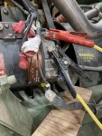
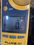
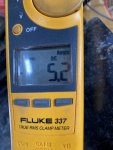
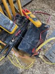
I did the external battery test today. See pics. Fun and interesting times in the barn lab! no smoke or sparks were seen 😉

I used 2 x 100ah deep cell AGM batteries that were 45-50% charged per the batt tester. They read 12.55 on volts.

The results were similar but on a smaller scale as the charge current was only running 5-6amps max. I previously ran the truck up to temperature then shut off and reconnected the alt to the external setup.

At first, the volts went to 28 and 14.2 with some small ripple. But the amps flowing thru the negative lead were over the place between 0-6. I tried the other ammeter but it did the same thing. The volt recording showed max went to 14.85 and 29.3 over the 5min period of testing. It seemed to creep up but not as far or as fast as when connected to the truck. That charge amperage has no reason to jump like that. These 2 batteries should be taking a charge steadily, albeit small.

when I warmed up the engine, the volts eventually crept up to 15.8 and 28.9. So higher when in the truck. The charge current is also very wobbly when in the truck. 14-21Amps and wildly varying.

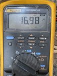
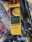
Another learning item: that AIH heater is pulling 95Amps on the probe when it slams on. Wtf! After the first long duty cycle of the AIH, where the amps on the probe were 95 and the alt ground strap was only showing 55, upon AIH cutout, the 14v leg spiked to 16.98 on the recording and ovco'd. I reset the E, then it settled back to 15.8ish. Then, watching the AIH turn on and off, the voltages swapped from 25.2 / 13.6 to 28.8 / 15.8. The power draw of that AIH makes that alternator groan pretty loudly. 95A slamming on and off. That's a problem imo. Why is that not SCR controlled to relieve that surging? Seems like a cheapo way to control that device with just that switching solenoid.

the lack of surging AIH load on the remote batt test setup is probably why the voltages were more stable. When I lift the 28v batt lead from alt to ext batt setup (leaving the 14 connected), the voltages remain stable, but when I reconnect, then the amperage goes even more wild, but voltages stay under 29 / 15.

95A * 25V = 2375W. Is that AIH that big? I don't have any #'s on that. Yowza!

I'm thinking if the alt has a failing rectifier then the voltage would be more wobbly. Seems like another issue in the alt that's making that current go crazy, enough to overwhelm the VR's ability to adjust.

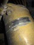
I'm going to have to pull it. The shaft on the 150a Cat alt I have is 7/8" smooth. So I'll see if the neihoff
fits first.


Attachments

MatthewWBailey

Father, Husband and Barn Hermit
Steel Soldiers Supporter
355
856
93
Location
Mesa, Colorado
I did the external battery test today. See pics. Fun and interesting times in the barn lab! no smoke or sparks were seen 😉

I used 2 x 100ah deep cell AGM batteries that were 45-50% charged per the batt tester. They read 12.55 on volts.

The results were similar but on a smaller scale as the charge current was only running 5-6amps max. I previously ran the truck up to temperature then shut off and reconnected the alt to the external setup.

At first, the volts went to 28 and 14.2 with some small ripple. But the amps flowing thru the negative lead were over the place between 0-6. I tried the other ammeter but it did the same thing. The volt recording showed max went to 14.85 and 29.3 over the 5min period of testing. It seemed to creep up but not as far or as fast as when connected to the truck. That charge amperage has no reason to jump like that. These 2 batteries should be taking a charge steadily, albeit small.

when I warmed up the engine, the volts eventually crept up to 15.8 and 28.9. So higher when in the truck. The charge current is also very wobbly when in the truck. 14-21Amps and wildly varying.

Another learning item: that AIH heater is pulling 95Amps on the probe when it slams on. Wtf! After the first long duty cycle of the AIH, where the amps on the probe were 95 and the alt ground strap was only showing 55, upon AIH cutout, the 14v leg spiked to 16.98 on the recording and ovco'd. I reset the E, then it settled back to 15.8ish. Then, watching the AIH turn on and off, the voltages swapped from 25.2 / 13.6 to 28.8 / 15.8. The power draw of that AIH makes that alternator groan pretty loudly. 95A slamming on and off. That's a problem imo. Why is that not SCR controlled to relieve that surging? Seems like a cheapo way to control that device with just that switching solenoid.

the lack of surging AIH load on the remote batt test setup is probably why the voltages were more stable. When I lift the 28v batt lead from alt to ext batt setup (leaving the 14 connected), the voltages remain stable, but when I reconnect, then the amperage goes even more wild, but voltages stay under 29 / 15.

95A * 25V = 2375W. Is that AIH that big? I don't have any #'s on that. Yowza!

I'm thinking if the alt has a failing rectifier then the voltage would be more wobbly. Seems like another issue in the alt that's making that current go crazy, enough to overwhelm the VR's ability to adjust.

I'm going to have to pull it. The shaft on the 150a Cat alt I have is 7/8" smooth. So I'll see if the neihoff
fits first.


GeneralDisorder

Well-known member
Steel Soldiers Supporter
1,469
4,097
113
Location
Portland, OR
So, since the 12v/24v 100a alternator isn't providing 70 - 90a @ 24v the batteries are making up the difference?
Right. The batteries are expected to pickup this intermittent load and then be recharged by the alternator. The alt will likely go to 100%+ operation (not 100A because engine is at idle immediately after start) for a bit till the AIH turns off. Shouldn't hurt it for the short time it's on and since the alt is probably ambient temp it's not in any danger of overheating - heat being the primary killer of heavily/over-loaded generators and motors.
 

Lostchain

Well-known member
Steel Soldiers Supporter
238
504
93
Location
Portland, OR
I've watched this video like 5 times now, looks perfectly normal. what exactly is the problem?
I tested a never used NOS '07 regulator yesterday on the bench with an identical setup to yours, and it behaves the same.

 
Last edited:

MatthewWBailey

Father, Husband and Barn Hermit
Steel Soldiers Supporter
355
856
93
Location
Mesa, Colorado
I've watched this video like 5 times now, looks perfectly normal. what exactly is the problem?
I tested a never used NOS '07 regulator yesterday on the bench with an identical setup to yours, and it behaves the same.

Does the current fluctuate with just batteries connected? That's what I took from this test. That should not be happening. And after running for about 15minutes, even with 28.8volts, those 2 batteries were not charged any more than when I started, per the batt tester. The alt is not producing. It should top off those 2 batts in short order. Im wondering if it got ruined when this thread was originally begun, which is when the starter solenoid welded, the AIH ran full bore bc it was 10F, and the system browned out at around 10volts. That event initiated this whole crusade. Before that, I had nada issues with voltage or anything. MF plunger nut!!!🤬
 

Lostchain

Well-known member
Steel Soldiers Supporter
238
504
93
Location
Portland, OR
And after running for about 15minutes, even with 28.8volts, those 2 batteries were not charged any more than when I started, per the batt tester. The alt is not producing. It should top off those 2 batts in short order.
This is where you lose me a bit. If the batteries are at 28.8V and they aren't taking a charge, doesn't that point to a problem within the batteries? If the batteries were drawing current and the alternator wasn't producing, wouldn't the voltage drop?
 

MatthewWBailey

Father, Husband and Barn Hermit
Steel Soldiers Supporter
355
856
93
Location
Mesa, Colorado
This is where you lose me a bit. If the batteries are at 28.8V and they aren't taking a charge, doesn't that point to a problem within the batteries? If the batteries were drawing current and the alternator wasn't producing, wouldn't the voltage drop?
Sorry I'm rush typing. The batts were at 24.8ish as a set before connecting. My system voltage was 28.8 coming from the alt. The non producing part is within the alt. It's producing voltage, but not meaningful power, at least not at 0-6 fluctuating amps on the probe. I think it's shorting somehow. The amps are not steady at all. There's a few different ways of failure that an alt can produce voltage but no real power. I should be getting 20-30amps of charge current into those 2 batteries as they're only 40-50% charged.
 

Lostchain

Well-known member
Steel Soldiers Supporter
238
504
93
Location
Portland, OR
Sorry I'm rush typing. The batts were at 24.8ish as a set before connecting. My system voltage was 28.8 coming from the alt. The non producing part is within the alt. It's producing voltage, but not meaningful power, at least not at 0-6 fluctuating amps on the probe. I think it's shorting somehow. The amps are not steady at all. There's a few different ways of failure that an alt can produce voltage but no real power. I should be getting 20-30amps of charge current into those 2 batteries as they're only 40-50% charged.
OK I understand now, thanks. I usually keep my bench test batteries topped off so my alternator doesn't stall out my test motor. I will drag them down a little bit and then re-test with a clamp meter and see if my older regulator outputs consistent current. I want to make sure I can catch a failure like yours on my setup. Appreciate the info.
 
Top
AdBlock Detected

We get it, advertisements are annoying!

Sure, ad-blocking software does a great job at blocking ads, but it also blocks useful features of our website like our supporting vendors. Their ads help keep Steel Soldiers going. Please consider disabling your ad blockers for the site. Thanks!

I've Disabled AdBlock
No Thanks