

Rooper90
New member
- 6
- 11
- 3
- Location
- Liberec Czech Republic
Hello!
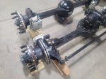
I'm looking for the best possible photos of the lower part of the V-100 Commando hull, preferably around the front and rear axles.
I'm a modeller and I'd like to build the most faithful replica of the V-100 in 1/35th scale. I have the Hobby Boss XM706E2 kit but unfortunately the lower part of the hull is completely wrong and doesn't match the real machine.
I already have a few photos of the lower part, but unfortunately I'm still not able to faithfully capture the quite complex V-100 "chassis."
Thank you very much for any help.
PS: If it doesn't belong in this forum, please forgive me.
George K.
")


.JPG")

.JPG")
.JPG")
.JPG")
.JPG")
.JPG")

