Man I really don’t get how these postings turn into this... I don’t mean to offend anyone with this posting but this keyboard cowboy crap is not helping anyone fix anything!
Guys you should be ashamed of yourselves!!! Why has no one made reference to the TM and the trouble shooting steps associated with the glow plug system? Here shortly the next posting will be that his glow plug controller (or worse) has failed due to tinkering.
Most failures on CUCV electrical systems are owner inflicted!!! Put the tools down and pick up the TM!!!
Go get the TM... read the step by step... test exactly as they say... come back and ask if something seems out of place or skewed. 100$ says anyone whom does this will find the problem 97% of the time as long as you have a general knowledge of electrical, meters, testing, mechanics and common sense... If not... Owning a Craftsman tool set you got for Xmas and a CUCV does not qualify you to be under the hood of a MV, you will create more damage than you will do good! Go get help... Take it to someone qualified... but do not start crawling around poking and prodding!!!
As for the rest of this...
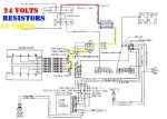
There is no way you’re going to get 24V flowing through a set of these resistors while under load... unless you’re putting about 48V through them, something is wired wrong, your plugs are dead, or you’re not testing them properly. If you’re sitting there with a volt meter hooked to the end of them reading 24V look at the wiring diagram... of course you have 24V on both sides!
If you hook a meter to one end of the resistor and then the other you’re going to get 0 ohms as your testing a dead short. If you didn’t have 0 ohms the resistor would be bad!
If the resistor was bad it would have a nice burned out spot in the windings on one or the other or both but at no time is a bad resistor going to allow a higher than normal voltage to flow across it... it will be LESS or none at all.
Wellman plugs are nothing special... As a matter of fact the TM it's self specs AC Delco 13G plugs. Stop with the wives tails and BS!!! As long as you are using a QUALITY replacement plug your fine!!!
"Glow Plugs. Operate as part of electrical system and assist in engine starting in cold
weather. Temperature self-regulating AC 13G glow plugs preheat air in precombustion chambers
prior to combustion"
The TM also specs testing your glow plugs every 6 months... Resistance should be 1-3 ohms... No one ever does this, one fails, then another and another. Everyone prefers to just keep cranking and prematurely bring their starter or glow plug controller to a early death... usually while blaming the 24V system for being the issue.
Guys this is SIMPLE SIMPLE SIMPLE stuff… I could build one of these wiring harnesses in my sleep! There is nothing complicated about them, they are so primitively put together it’s not funny… basic.. simple.. cheap and VERY effective!!!
GLOW PLUG SYSTEM
NOTE
Glow plug system cycling can be detected by Iistening for clicking at glow
plug relay or by observing voltmeter. Indicator should be to the left of the
normal range during cycling and return to normal range after cycling.
15. GLOW PLUG MODULE INOPERATIVE
NOTE
The only way to determine if your glow plug module is operating properly is
through testing. The glow plug module should not be replaced until the
following tests are performed.
clean, and
continuity.
Step 1. Disconnect pink wire from fuel injector pump. Remove printed circuit board from
glow plug module. Check each circuit to the glow plug module as described. Trace
any circuit that does not operate properly. (See wiring diagram F-7 or F-") If all
circuits operate properly, replace glow plug module. (See paragraph 4-
2-62 Change 2
TM 9-2320-289-20
Table 2-4. Electrical Troubleshooting (Con’t)
MALFUNCTION
TEST OR INSPECTION
CORRECTIVE ACTION
Wire Color Key Position Instructions and Normal Results
Purple/white “START“ Approximately 12.0 volts at wire. If voltage
is not correct, trace circuit.
Light blue “ RUN “ Jump wire to ground; glow plug relay
energizes. If relay does not energize, trace
circuit. If circuit is good, replace relay. (See
paragraph 4-
Dark blue
Pink/black
Orange
Yellow
"RUN“
“RUN“
“RUN“
“OFF”
Jump wire to ground; “WAIT” light turns on.
If “WAIT” light does not turn on, replace
bulb. (See paragraph 4-7) If “WAIT” light
still does not turn on, trace circuit.
Approximately 12.0 volts at wire. If voltage
is not correct, trace circuit.
Jump light blue wire to ground;
Approximately 12.0 volts at orange wire. If
voltage is not correct, trace circuit.
800 ohms (minimum) at wire (engine cold).
If resistance is not correct, trace circuit. If
resistance is still not correct, replace glow
plug switch. (See paragraph 3-20)
Black "OFF" 0 ohms at wire. Clean connection and
tighten if not correct.
Pink/black and “OFF” 6-10 ohms between wires. If resistance is
light blue at not correct, replace glow plug relay. (See
glow plug relay paragraph 4-
16. “WAIT” LIGHT INOPERATIVE (ENGINE COLD)
Step 1. Check 20 amp engine control fuse and 20 amp ignition fuse. (See
paragraph 4-12)
Replace fuse if burned out.
2-63
TM 9-2320-28$20
Table 2-4. Electrical Troubleshooting (Con't)
MALFUNCTION
TEST OR INSPECTION
CORRECTIVE ACTION
CAUTION
Do not leave key in "RUN” position for more than 2 minutes. Failure to
follow this caution may resuit in damage to glow plugs.
Step 2. Remove glow plug modu!e. (See paragraph 4- Turn key to “RUN” position. Using
jumper wire, ground dark blue lead.
If “WAIT” light turns on, turn key to “OFF” position, reinstall glow plug module,
and perform step 3.
If “WAll
-” light does not turn on, replace bulb. If “WAIT” light still does not turn
cm, trace circuit. (See wiring diagram F-7 or F-
Step 3. Turn key to “RUN” position. Disconnect connector from glow plug switch on upper
left rear of cylinder head.
If “WAIT” light turns on, replace glow plug switch. (See paragraph 3-20)
If “WAIT” light does not turn on, perform
Electrical Troubleshooting malfunction
#15
17. “WAIT” LIGHT ON CONTINUOUSLY WITH KEY IN “RUN” POSITION
Step 1. Remove glow plug module
If “WAIT” light stays on, trace circuit through dark blue lead to “WAIT” light.
(See wiring diagram F-7 or F-
If “WAIT” light goes out, perform
Electrical Troubleshooting malfunction #15.
18. "WAIT” LIGHT OPERATES UPON RESTARTING (ENGINE HOT)
Step 1. Check connections at glow plug switch on upper left rear of cylinder head and glow
plug module.
If connections are not good, clean and secure all connectors.
If connections are good, perform
Electrical Troubleshooting malfunction #15.
19. ENGINE CRANKS BUT WILL NOT START; ENGINE COLD; “WAIT” LIGHT OPERATES
Step 1. Ensure that key is in “OFF” position. Check for voltage between glow plug relay
terminal where orange lead connects and ground.
If there
IS voltage, replace glow plug relay (see paragraph 4- and perform
step 3.
If there is no voltage, perform step 3.
2-64 Change 2
TM 9-2320-289-20
Table 2-4. Electrical Troubleshooting (Con’t)
MALFUNCTlON
TEST OR INSPECTlON
CORRECTIVE ACTlON
CAUTION
DO NOT leave key in “RUN” position for more than 2 minutes. Failure to
follow this caution may result in damage to glow plugs.
Step 2. Turn key to “RUN” position. Check for voltage between glow plug relay terminal
where orange lead connects and ground.
NOTE
Glow plugs will cycle to 0 volts in approximately 20 seconds after first
operation. Time will shorten as glow plugs become hotter.
If there are 10.0-15.0 volts, ensure that engine is mechanically sound and fuel
system is operating properly,
If there are 22.0-28.0 volts, perform step 3.
If there is no voltage, perform step 4.
Step 3. Disconnect each glow plug lead and check for resistance between glow plug terminal
and ground. Resistance should be 1-3 ohms. Check glow plugs for looseness or
damage.
If any glow plug does not have correct resistance or is damaged, replace, (See
paragraph 3-20) Tighten any loose glow plugs.
Step 4. Tag and disconnect all glow plug leads from glow plugs. Check for voltage between
glow plug relay terminal where red lead connects and ground.
If voltage is 10.0-15.0 volts, connect glow plug leads and start engine.
If voltage is 22,0-28.0 volts, perform step 5.
If there is no voltage, trace circuit back to positive terminal board. (See wiring
diagram F-7 or F-
Change 2 2-65
TM 9-2320-289-20
Table 2-4. Electrical Troubleshooting (Con’t)
MALFUNCTION
TEST OR INSPECTION
CORRECTIVE ACTION
WARNING
Resistor may be hot. Use care when performing this step or injury to
personnel may occur.
Step 5.
Step 6.
Step 7.
Step 8.
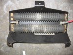
Disconnect batteries, pull out bracket and resistor assembly (see paragraph 4-44,
REMOVAL, step 4), disconnect output (red wire) from relay, disconnect input (blue
wire) from input to resistors. Connect positive lead of multimeter to blue wire;
connect negative lead to red wire. Check resistance between resistors and ground.
Resistance should be 0.28 ohms.
If resistance is not correct, replace resistor, connect glow plug leads and
perform step 6.
If resistance is correct, connect glow plug leads and perform step 6.
Check for voltage between glow plug relay terminal where pink/black lead connects
and ground.
If there is voltage, perform step 7.
If there is no voltage, trace circuit. (See wiring diagram F-7 or F-
Check for voltage between glow plug relay terminal where light blue lead connects
and ground.
If there is voltage, perform step 8.
If there is no voltage, replace glow plug relay. (See paragraph 4-
Check for voltage at light blue lead on glow plug module.
If there is no voltage, trace circuit (See wiring diagram F-7 or F-
If there is voltage, perform
Electrical Troubleshooting malfunction #15.
2-65.0/(
If all
circuits operate properly, replace glow plug module. (See paragraph 4-
2-62 Change 2
TM 9-2320-289-20
Table 2-4. Electrical Troubleshooting (Con’t)
MALFUNCTION
TEST OR INSPECTION
CORRECTIVE ACTION
Wire Color Key Position Instructions and Normal Results
Purple/white “START“ Approximately 12.0 volts at wire. If voltage
is not correct, trace circuit.
Light blue “ RUN “ Jump wire to ground; glow plug relay
energizes. If relay does not energize, trace
circuit. If circuit is good, replace relay. (See
paragraph 4-
Dark blue
Pink/black
Orange
Yellow
"RUN“
“RUN“
“RUN“
“OFF”
Jump wire to ground; “WAIT” light turns on.
If “WAIT” light does not turn on, replace
bulb. (See paragraph 4-7) If “WAIT” light
still does not turn on, trace circuit.
Approximately 12.0 volts at wire. If voltage
is not correct, trace circuit.
Jump light blue wire to ground;
Approximately 12.0 volts at orange wire. If
voltage is not correct, trace circuit.
800 ohms (minimum) at wire (engine cold).
If resistance is not correct, trace circuit. If
resistance is still not correct, replace glow
plug switch. (See paragraph 3-20)
Black "OFF" 0 ohms at wire. Clean connection and
tighten if not correct.
Pink/black and “OFF” 6-10 ohms between wires. If resistance is
light blue at not correct, replace glow plug relay. (See
glow plug relay paragraph 4-
16. “WAIT” LIGHT INOPERATIVE (ENGINE COLD)
Step 1. Check 20 amp engine control fuse and 20 amp ignition fuse. (See
paragraph 4-12)
Replace fuse if burned out.
2-63
TM 9-2320-28$20
Table 2-4. Electrical Troubleshooting (Con't)
MALFUNCTION
TEST OR INSPECTION
CORRECTIVE ACTION
CAUTION
Do not leave key in "RUN” position for more than 2 minutes. Failure to
follow this caution may resuit in damage to glow plugs.
Step 2. Remove glow plug modu!e. (See paragraph 4- Turn key to “RUN” position. Using
jumper wire, ground dark blue lead.
If “WAIT” light turns on, turn key to “OFF” position, reinstall glow plug module,
and perform step 3.
If “WAll
-” light does not turn on, replace bulb. If “WAIT” light still does not turn
cm, trace circuit. (See wiring diagram F-7 or F-
Step 3. Turn key to “RUN” position. Disconnect connector from glow plug switch on upper
left rear of cylinder head.
If “WAIT” light turns on, replace glow plug switch. (See paragraph 3-20)
If “WAIT” light does not turn on, perform
Electrical Troubleshooting malfunction
#15
17. “WAIT” LIGHT ON CONTINUOUSLY WITH KEY IN “RUN” POSITION
Step 1. Remove glow plug module
If “WAIT” light stays on, trace circuit through dark blue lead to “WAIT” light.
(See wiring diagram F-7 or F-
If “WAIT” light goes out, perform
Electrical Troubleshooting malfunction #15.
18. "WAIT” LIGHT OPERATES UPON RESTARTING (ENGINE HOT)
Step 1. Check connections at glow plug switch on upper left rear of cylinder head and glow
plug module.
If connections are not good, clean and secure all connectors.
If connections are good, perform
Electrical Troubleshooting malfunction #15.
19. ENGINE CRANKS BUT WILL NOT START; ENGINE COLD; “WAIT” LIGHT OPERATES
Step 1. Ensure that key is in “OFF” position. Check for voltage between glow plug relay
terminal where orange lead connects and ground.
If there
IS voltage, replace glow plug relay (see paragraph 4- and perform
step 3.
If there is no voltage, perform step 3.
2-64 Change 2
TM 9-2320-289-20
Table 2-4. Electrical Troubleshooting (Con’t)
MALFUNCTlON
TEST OR INSPECTlON
CORRECTIVE ACTlON
CAUTION
DO NOT leave key in “RUN” position for more than 2 minutes. Failure to
follow this caution may result in damage to glow plugs.
Step 2. Turn key to “RUN” position. Check for voltage between glow plug relay terminal
where orange lead connects and ground.
NOTE
Glow plugs will cycle to 0 volts in approximately 20 seconds after first
operation. Time will shorten as glow plugs become hotter.
If there are 10.0-15.0 volts, ensure that engine is mechanically sound and fuel
system is operating properly,
If there are 22.0-28.0 volts, perform step 3.
If there is no voltage, perform step 4.
Step 3. Disconnect each glow plug lead and check for resistance between glow plug terminal
and ground. Resistance should be 1-3 ohms. Check glow plugs for looseness or
damage.
If any glow plug does not have correct resistance or is damaged, replace, (See
paragraph 3-20) Tighten any loose glow plugs.
Step 4. Tag and disconnect all glow plug leads from glow plugs. Check for voltage between
glow plug relay terminal where red lead connects and ground.
If voltage is 10.0-15.0 volts, connect glow plug leads and start engine.
If voltage is 22,0-28.0 volts, perform step 5.
If there is no voltage, trace circuit back to positive terminal board. (See wiring
diagram F-7 or F-
Change 2 2-65
TM 9-2320-289-20
Table 2-4. Electrical Troubleshooting (Con’t)
MALFUNCTION
TEST OR INSPECTION
CORRECTIVE ACTION
WARNING
Resistor may be hot. Use care when performing this step or injury to
personnel may occur.
Step 5.
Step 6.
Step 7.
Step 8.
Disconnect batteries, pull out bracket and resistor assembly (see paragraph 4-44,
REMOVAL, step 4), disconnect output (red wire) from relay, disconnect input (blue
wire) from input to resistors. Connect positive lead of multimeter to blue wire;
connect negative lead to red wire. Check resistance between resistors and ground.
Resistance should be 0.28 ohms.
If resistance is not correct, replace resistor, connect glow plug leads and
perform step 6.
If resistance is correct, connect glow plug leads and perform step 6.
Check for voltage between glow plug relay terminal where pink/black lead connects
and ground.
If there is voltage, perform step 7.
If there is no voltage, trace circuit. (See wiring diagram F-7 or F-
Check for voltage between glow plug relay terminal where light blue lead connects
and ground.
If there is voltage, perform step 8.
If there is no voltage, replace glow plug relay. (See paragraph 4-
Check for voltage at light blue lead on glow plug module.
If there is no voltage, trace circuit (See wiring diagram F-7 or F-
If there is voltage, perform
Electrical Troubleshooting malfunction #15.
2-65.0/(
Okay... went through these test procedures, I have hard copies of all manuals, but I seem to have a different issue I cannot seem to find on here. Used search but most GP issues I found do not address this problem directly as far as I cold find.
84 CUCV M1009, complete with functional radios and intercom system, all US military wiring and harnesses.Original vehicle, original harnesses, colours match on everything so far so it appears to be not screwed with under dash or in engine bay. trailer lights all work when connected. (Other than the resistors have been bypassed and hooked in correctly. 12 v to GP relayq1.) Temp sensor replaced as part of my troubleshooting, as I thought this may be the issue. I have verified with voltmeter that all glow glow plug resistance is correct per TM manual troubleshooting (the above list was much easier then going through all the manuals)
I have new Hillbilly Wizard card, but same problem existed with old card. Have had vehicle since 2015 this is a recent problem.
Vehicle starts correctly, glow plug process works perfectly, goes to low idle with no issues. HOWEVER... if ANY electrical switch is activated (wiper motor, blinker, brake pedal, headlights, etc) is activated the glow plugs immediately try to warm up again. As soon as any of the electrical items are turned off, the warming stops. I can visually verify by watching red LED on card light up, and also hear the GP relay turn on/off. Voltmeter drops slightly, about a 1/32 movement (but stays in green).
if I pull the GP card out as soon as the slow pugs are warm, prior to switch on, there is no issue, vehicle operated with no problems. This is was my only way to verify that it indeed connected to the card in some fashion, since i cannot seem to find what is "telling" the card that it needs to re-start warm up.
I have a list of all 34 ground points on vehicle, and so far have not found any issues yet under dash with rubbed or cut wires, etc.
Other than putting a manual push button momentary switch on the power to the glow plug card so that it only gets power as long as the button is pressed (so I don't have to manual;y remove the card every time) I cannot find what is going on. I would rather not start really taking apart 39 year old harnesses if I don't have to, and I really want to keep this in "original" condition.
However... if the only answer is install the power bypass to the GP card, then so be it. I think the best place to put the button would be on the plastic on the backside of the blinker assembly so it is not obvious 9also wold act as an anti-theft device if you didn't know it was there).
Thanks for patience and any replies.