• Steel Soldiers now has a few new forums, read more about it at: New Munitions Forums!

  • Microsoft MSN, Live, Hotmail, Outlook email users may not be receiving emails. We are working to resolve this issue. Please add support@steelsoldiers.com to your trusted contacts.

M1078 Remote Spotlights....

Littlejacy

New member
22
7
3
Location
Amado, AZ
Hey all! Has anyone used a COBO Remote Spotlight on their M1078?? Yes, I bought one off Ebay, brand new. Guy gave me instructions, and I believe I have the necessary supplies. However, has anyone DONE this before, and doeas anyone have a detailed presentation of HOW they wired it. The instructions all sound good until you start looking at everything, lol!
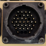
Is there a preferred system, such as an ibis tek system? My whole thing is this: This COBO light has a 6-pin amphenol (military) connector that if I could, would like to just wire up to a like-connected controller. Does one exist? Would/could it wire up to a Ibis-Tek controller that I find on Ebay??
 

ZiggyO

Well-known member
Steel Soldiers Supporter
647
517
93
Location
Nebraska
I will hazard a guess that you probably bought that light from me......... There is a standalone controller but it is so rare that I have only seen one in my 22+ years of playing with this stuff-- most of the controls were integrated into the armored vehicles that these would have been used on....... That being said, it is fairly straightforward to wire if you break it down--vertical axis is controlled by a dc motor-- which direction it goes is a function of reversing polarity, the horizontal axis is the same........the simplest control circuit then would be 2 momentary dpdt switches, one for each axis. If you are a little more tech minded, you can make use of a solid state h-bridge to achieve the same effect. Since most common joysticks are single pole microswitches at each axis point, you would need to use relays (or again a solid state H-bridge).

As to whether or not it would work with an ibistek control head, maybe-- you would have to look at how it is wired and possibly be ready to change the configuration to match.

I actually am working on a simple standalone joystick for these but it is way down on my list of stuff to do -- so far, I have drawn out a rough schematic and ordered some components that are collecting dust on my workbench.............

Z
 

Littlejacy

New member
22
7
3
Location
Amado, AZ
I will hazard a guess that you probably bought that light from me......... There is a standalone controller but it is so rare that I have only seen one in my 22+ years of playing with this stuff-- most of the controls were integrated into the armored vehicles that these would have been used on....... That being said, it is fairly straightforward to wire if you break it down--vertical axis is controlled by a dc motor-- which direction it goes is a function of reversing polarity, the horizontal axis is the same........the simplest control circuit then would be 2 momentary dpdt switches, one for each axis. If you are a little more tech minded, you can make use of a solid state h-bridge to achieve the same effect. Since most common joysticks are single pole microswitches at each axis point, you would need to use relays (or again a solid state H-bridge).

As to whether or not it would work with an ibistek control head, maybe-- you would have to look at how it is wired and possibly be ready to change the configuration to match.

I actually am working on a simple standalone joystick for these but it is way down on my list of stuff to do -- so far, I have drawn out a rough schematic and ordered some components that are collecting dust on my workbench.............

Z
Ha! You must be the one, lol! I'll tell ya, this light is absolutely sweet! I also saw the video on Youtube and thought, damn! that's what I need. I see your included schematic in the literature. Bear with me here, as I'm mechanically inclined, I'm new to this type of vehicle (which is actually kind of refreshing!).

1. From my 24+ I need to run a 15A fused lead to a switch....let's call it the "power" switch.

2. Jump two poles on DPDT switches and connect to the "power" switch. (+)

3. Jump two poles on DPDT switches and connect to the "power" switch. (-)

4. Two leads on first DPDT switch to corresponding wires on light harness for elevation.

5. Two leads on second DPDT switch to corresponding wires on light harness for traverse.

I am using a length of CAT5 cable as the included harness with the light is too short of course, plus well you guessed it, will not plug into anything on a M1078.
Are the two "power" wires (the two white wires) on the unit, connecting to the same power terminals on the DPDT switches? Or actually, just to the "power" switch I'd guess.
By the diagram, it doesn't appear that I am utilizing all 8 strands of CAT5. Am I misreading this?
 
Last edited:

ZiggyO

Well-known member
Steel Soldiers Supporter
647
517
93
Location
Nebraska
That is correct....... I just suggested in my original schematic using a cat 5 cable because it is the easiest thing that's off the shelf and plug-n-play....... If you have access to a crimping tool, and the plugs, you can make up your own cable as well........

Z
 

Littlejacy

New member
22
7
3
Location
Amado, AZ
That is correct....... I just suggested in my original schematic using a cat 5 cable because it is the easiest thing that's off the shelf and plug-n-play....... If you have access to a crimping tool, and the plugs, you can make up your own cable as well........

Z
Okay, too be sure: I can completely remove that factory harness (minus the two white power leads) and use my determined length of CAT5 cable?
 

ZiggyO

Well-known member
Steel Soldiers Supporter
647
517
93
Location
Nebraska
yes-- when pulling out the factory harness, you may have to use a small pick to pull back the springy clip part of the rj45 plug-- also, the two white wires are the power in-- they are held in place with screw clamp terminals-- you can replace these with any length you choose as well......

Z
 

Littlejacy

New member
22
7
3
Location
Amado, AZ
yes-- when pulling out the factory harness, you may have to use a small pick to pull back the springy clip part of the rj45 plug-- also, the two white wires are the power in-- they are held in place with screw clamp terminals-- you can replace these with any length you choose as well......

Z
Excellent!! Thank-you so much for taking the time to "spoon feed" me the information, can't wait to get this thing working!
 

coachgeo

Well-known member
5,205
3,543
113
Location
North of Cincy OH
Excellent!! Thank-you so much for taking the time to "spoon feed" me the information, can't wait to get this thing working!
how is your hook up going? I just bought several Ibis .... not sure if they are the same / similar or not.

Actually want to attach my side view cameras to two them as well. then one on cab and one on back (also with cameras.)

would like to be able to use remote movement WITHOUT light on too. (dont need except at night)

btw.... a video was mentioned..... you got link to this video? not finding it
 
Last edited:

coachgeo

Well-known member
5,205
3,543
113
Location
North of Cincy OH
....

I actually am working on a simple standalone joystick for these but it is way down on my list of stuff to do -- so far, I have drawn out a rough schematic and ordered some components that are collecting dust on my workbench.............

Z
any updates? did covid give you some time to play with this?
 

ZiggyO

Well-known member
Steel Soldiers Supporter
647
517
93
Location
Nebraska
Honestly, its so far down my list that I will be lucky to start playing with it again later this summer.......... (Then again, I am getting caught up on stuff due to the stay home orders, but I am also doing alot of stuff for family that is vulnerable).............

Z
 

coachgeo

Well-known member
5,205
3,543
113
Location
North of Cincy OH
Found this. for the Black Ibis Tek pan/tilts. ...... not sure how accurate. Apologize and didnt realize COBO was something entirely different.. Thought they were a different version of an Ibis Tek product.


For those who might be interested, here are the pins and related info. Hit me up PM if you have questions.
Wires in the supplied harness.
Pins
1 - Red
2- Brown
3 - Yellow
4- Blue
5- purple
6-white
7-green
8- red - to 24v Positive
9-black - to Ground/Neg
Connect 1, 7, and 9 to ground.
First Switch A: Connect an On/Off toggle switch on wire 8 (pos) to power unit up. This enables IR lights and Pan/Tilt
Second Switch B on wire 6(pos) to 24v power to illuminate the HID.
I added a third Switch C (Master switch) that cuts all power to my control panel.
Direction is enabled when one or both switches A&B are on. (Pan tilt works with switch A on, or switch A & B on.) By grounding the connections to 2,3,4,5 enabling pan/tilt. I ran a wire from Pin 7 & (2,3,4,5) to the joystick. When you move the joystick in a direction, it grounds the circuit, and results in up/down/left/right.

from
 
Last edited:

radioguy971

New member
13
1
3
Location
Webster ny
Found this....... not sure how accurate


For those who might be interested, here are the pins and related info. Hit me up PM if you have questions.
Wires in the supplied harness.
Pins
1 - Red
2- Brown
3 - Yellow
4- Blue
5- purple
6-white
7-green
8- red - to 24v Positive
9-black - to Ground/Neg
Connect 1, 7, and 9 to ground.
First Switch A: Connect an On/Off toggle switch on wire 8 (pos) to power unit up. This enables IR lights and Pan/Tilt
Second Switch B on wire 6(pos) to 24v power to illuminate the HID.
I added a third Switch C (Master switch) that cuts all power to my control panel.
Direction is enabled when one or both switches A&B are on. (Pan tilt works with switch A on, or switch A & B on.) By grounding the connections to 2,3,4,5 enabling pan/tilt. I ran a wire from Pin 7 & (2,3,4,5) to the joystick. When you move the joystick in a direction, it grounds the circuit, and results in up/down/left/right.

from
do you happen to know the pinout of this connector. Id want to add a pan/ tilt search light to my current wire harness.

my plan is to open up the wiring harness, find the terminal pins I need, crimp terminal pins onto a wire and plug it in to the main wire harness connector that plugs into the controller


Thanks for your time!!
 

Attachments

coachgeo

Well-known member
5,205
3,543
113
Location
North of Cincy OH
do you happen to know the pinout of this connector. Id want to add a pan/ tilt search light to my current wire harness.

my plan is to open up the wiring harness, find the terminal pins I need, crimp terminal pins onto a wire and plug it in to the main wire harness connector that plugs into the controller


Thanks for your time!!
below is all I got on the pan tilt version..... from facebook and he was making his own controller for them

For those who might be interested, here are the pins and related info. Hit me up PM if you have questions.
Wires in the supplied harness. (NOTE: am not sure if "supplied harness" = the tiny harness that often ships w/ each light- about 6" long .... or a seperate long harness he happened to have acquired)
Pins
1 - Red
2- Brown
3 - Yellow
4- Blue
5- purple
6-white
7-green
8- red - to 24v Positive
9-black - to Ground/Neg
Connect 1, 7, and 9 to ground.
First Switch A: Connect an On/Off toggle switch on wire 8 (pos) to power unit up. This enables IR lights and Pan/Tilt
Second Switch B on wire 6(pos) to 24v power to illuminate the HID.
I added a third Switch C (Master switch) that cuts all power to my control panel.
Direction is enabled when one or both switches A&B are on. (Pan tilt works with switch A on, or switch A & B on.) By grounding the connections to 2,3,4,5 enabling pan/tilt. I ran a wire from Pin 7 & (2,3,4,5) to the joystick. When you move the joystick in a direction, it grounds the circuit, and results in up/down/left/right.

suggested joystick that is:
"Momentary type operation with 1 normally open contact per direction"
one that another used successfully specs
Model: HKA1-41Z04
Rated Voltage: 150V / 250V / 600V
Rated Current: 15A / 10A / 5A
Action Type: Momentary
Positions: 4
Contacts Type: 1 NO Contact Per Direction
Terminals Type: Screw Clamps Terminals
Panel Mounting Diameter: 30mm / 1-17/94"
Overall Size: 145 x 49mm / 5.71" x 1.93" (L*D)
Joystick Length: 78mm / 3.07"


Info from https://www.facebook.com/groups/hmm...xBE_Lf1x5ThOaRHqKJA2tvBTyruEiIOag&__tn__=R]-R
 
Last edited:

ZiggyO

Well-known member
Steel Soldiers Supporter
647
517
93
Location
Nebraska
I haven't dug into the harnesses for the ibis tek lights that much-- I got alot further with the cobo lights. That being said, from what I do see, they operate on a similar principle: two reversible dc drives, one each for pan/tilt. The joystick you linked to should work nicely with a good overkill factor on the contacts (which given today's chinesium content in most electronics, probably halves your effective current rating right out of the gate). Whether the pinouts you gave above are correct for the ibis tek lights, I do not know.

Z
 

coachgeo

Well-known member
5,205
3,543
113
Location
North of Cincy OH
I haven't dug into the harnesses for the ibis tek lights that much-- I got alot further with the cobo lights. That being said, from what I do see, they operate on a similar principle: two reversible dc drives, one each for pan/tilt. The joystick you linked to should work nicely with a good overkill factor on the contacts (which given today's chinesium content in most electronics, probably halves your effective current rating right out of the gate). Whether the pinouts you gave above are correct for the ibis tek lights, I do not know.

Z
my bad... I though Cobo was some Military slang for newer versions of these lights..... didn't catch that it was a completely separate manufacture.
 

ZiggyO

Well-known member
Steel Soldiers Supporter
647
517
93
Location
Nebraska
No, the cobo lights are made in Italy and are visible light only. They are also more compact than the ibis tek lights and have a clear dome protecting them.
 
Top
AdBlock Detected

We get it, advertisements are annoying!

Sure, ad-blocking software does a great job at blocking ads, but it also blocks useful features of our website like our supporting vendors. Their ads help keep Steel Soldiers going. Please consider disabling your ad blockers for the site. Thanks!

I've Disabled AdBlock
No Thanks