• Steel Soldiers now has a few new forums, read more about it at: New Munitions Forums!

  • Microsoft MSN, Live, Hotmail, Outlook email users may not be receiving emails. We are working to resolve this issue. Please add support@steelsoldiers.com to your trusted contacts.


m1078 to A1 driveshaft parts source

johndoe007

Member
48
0
6
Location
New England, CT
Has anyone figured out what parts are necessary for the A1 upgrade to the drive train? I know about the high speed gears but am thinking I should probably fix the drive shaft first. Has anyone found a stash of them?
 

NDT

Well-known member
Steel Soldiers Supporter
10,171
5,871
113
Location
Camp Wood/LC, TX
A1's got the C7 engine, some got hydraulic front brakes. Axle ratio is unchanged. What other changes were made that you know of?
 

johndoe007

Member
48
0
6
Location
New England, CT
The easy ones should be the alternator upgrade and the driveshaft upgrade. I am mostly concerned about the drive shaft that vibrated and disconnected at speed that prompted the A1 upgrades. I am just wondering if anyone has figured out what drive shaft is part of the upgrade that Oshkosh is using.
 

NDT

Well-known member
Steel Soldiers Supporter
10,171
5,871
113
Location
Camp Wood/LC, TX
The driveshaft problem was solved 100% fleet-wide back in the 90's. Stewart and Stevenson had to go to the field and replace bellhousings and driveshafts on 100% of delivered vehicles. A "D" was stamped on the VIN plate to denote that. (There is a thread here on that subject). The A1 came about because Cat came up with the C7 electronic engine, and S&S thought it would be way cool to use it.
 

johndoe007

Member
48
0
6
Location
New England, CT
That report on the driveshaft in the link I included is dated 2002 and it said there were still problems with the A0 and A1 models and recommended going forward with a GKN Constant Velocity driveshaft. I am just wondering if anyone has found one, done the swap, and if that is what Oshkosh is currently using?
 

Oxyacetylene

Active member
Steel Soldiers Supporter
518
179
43
Location
Stoneville, NC
Interesting info in the doc you linked. I read through some of it. The LMTV rear driveshaft appears to be the most stressed, due to the length and angle. I haven't seen any photos showing a CV type shaft on the newer trucks, so I don't think that has been done on the FMTV's, but can't say for certain. I can only go based on what I have seen online and the couple A1 trucks I have seen in person.

I also found it interesting in the document how they described the test procedures, including accelerating to higher speeds to find the critical speed at which the driveshafts would be significantly more susceptible to damage. For the LMTV that speed was 68 MPH. They must have the high speed gears in their test rig! The critical speed has more to do with the driveshaft RPM's than how fast the truck is traveling, but you get the idea.
 

Lmtv772

Banned
651
18
0
Location
Florida
To the OP
All the LMTV have the upgraded driveshaft , Before the fix was done vehicles were not to go any faster than 35mph.
You can verify that the update has been done to the driveshaft, by a stamped D on the serial number plate left side of the steering wheel

View attachment 619119

Just saw NDT's response , which is essentially what I said :)
 
Last edited:

Overdrive

Active member
411
89
28
Location
Wentzville, Missouri
Also the "D" upgrade switched out bearing cup straps for the bolt on bearing caps as well as a 4" diameter shaft vs the 3" original so pretty quick to spot and verify the fix in addition to the big D on the data plate.

I read that entire test and evaluation report a while ago. As I recall the best solution, that wasn't used by the way, was the GKN solution with a driveshaft that had the ball and socket type joint (can't recall the name) that is the same type of shaft on the current Jeep wranglers.

Corrected my post meant GKN not BAE
 
Last edited:

scottmandu

Active member
822
35
28
Location
Texas
Also the "D" upgrade switched out bearing cup straps for the bolt on bearing caps as well as a 4" diameter shaft vs the 3" original so pretty quick to spot and verify the fix in addition to the big D on the data plate.
I think it was a Constant Velocity style joint.

Also the Later A1's (post 2008 IIRC) used the intermediate axle from the 6X6, instead of the rear axle of the 6X6.
 

coachgeo

Well-known member
4,976
3,342
113
Location
North of Cincy OH
Also the "D" upgrade switched out bearing cup straps for the bolt on bearing caps as well as a 4" diameter shaft vs the 3" original so pretty quick to spot and verify the fix in addition to the big D on the data plate.

I read that entire test and evaluation report a while ago. As I recall the best solution, that wasn't used by the way, was the BAE solution with a driveshaft that had the ball and socket type joint (can't recall the name) that is the same type of shaft on the current Jeep wranglers.
UPDATE- Apologize at writing my truck is 150 miles away thus could not look to verify if Yoke on T-case was machined to shaft or installed on splines. After much study of pictures and Parts book now confident to say they are on splines. Below updated accordingly

CV Joint (Constant Velocity). On these trucks the yoke is slipped onto output shaft of Tcase and bolted so it is just a matter of $$$, taking measurments and having a driveshaft made with Rzeppa style joints on each end. I've contaced GDK for part numbers of the joints they used but they've not responded.


Rzeppa style CV joint on end of a shaft. rzeppa.jpg
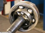
goal is to end up with more flexable joint like this sye3.jpg on each end that does not translate forces into the Tcase and alxle as much as a typeical Ujoint does.
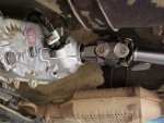
Note: Last photo is NOT exact (wrong joint pictured) but visually more self explanitory cause Rzeppa ball ends when installed are incased. Thus, actual shaft ends would be of Rzeppa CV type like pictured earlier; not Double Cardan CV shaft as shown


So without a huge market what do yall think??? To have a shaft made up, 1 grand? (may be WAYYYYYYYY off on that.) Sell price would be similar again cause not a big market????


For more tech info see..... http://www.billavista.com/tech/Articles/Driveshaft_Bible/index.html


Has anyone seen or have a good pic of the driveline proposed in the study. The PDF's pic. of the highest rank (Rzeppa type) shaft is not distinguishable in any of the PDF's have seen so far.
 

Attachments

Last edited:

Overdrive

Active member
411
89
28
Location
Wentzville, Missouri
LMTV772, I was referring to the GKN Rzeppa CV joint driveshaft that was submitted for the LMTV study. The one people are referring to is a double cardan CV joint with two hinged u joints. They also tried that one. Modern jeeps have the Rzeppa joint. I have experienced driveshafts bouncing down the interstate at 70mph on the old K5 blazers I used to own with 4" lift and tried the double Cardon CVs. Also messed with the Jeep TJ slip yoke eliminator and double cardon ds on that vehicle as well. It was fun splitting the tcase on the jeep and replacing the main shaft :)

As already stated in this thread the issue is terminal velocity of the spinning shaft due to the low gearing on the LMTV.

On another note. From my days lifting jeeps and blazers with crazy short drive lines and severe angles. You can do a simple check on the LMTV to see the point on the angle issue. Get a $4 magnetic angle finder and place it on each u joint on the pinion then the tcase output yoke with a flat part of the yoke horizontal so the angle finder sits flat. Write down each angle. For good u joint survival you want those angles to be within 3 degrees of each other max 2 degrees would be even better. This is standard driveline stuff. One idea I was toying with was to see if it was possible to place a 2 or 3 degree shim under the rear spring pack to point the rear pinion more towards the output yoke of the tcase. We did that all the time on leaf spring trucks to help with vibrations. If you look at your rear pinion with an unloaded truck it points flat or parallel with the ground and maybe a little down. Again, standard stuff in the offroad lifted truck world.

That report has a good summary on what the recommendations were as well as a ranking of pros and cons of each design.
 
Last edited:

coachgeo

Well-known member
4,976
3,342
113
Location
North of Cincy OH
... was referring to the BAE Rzeppa CV joint driveshaft that was submitted for the LMTV study. .....
recognized CV type mistake as you posted. Let the unclear pictures in the PDF throw me off. My bad. Updated earlier post.

On the OEM Tcase are the yokes machined into output shaft of the Tcase or are they slipped onto splines of the output shaft? Hope Spline fitted. Would make potential upgrade ton easier.
 
Last edited:

coachgeo

Well-known member
4,976
3,342
113
Location
North of Cincy OH
.... On the OEM Tcase are the yokes machined into output shaft of the Tcase or are they slipped onto splines of the output shaft? Hope Spline fitted. Would make potential upgrade ton easier.
Yes, Yoke is on splines.

Appologies it took awhile but finally found enough data to answer my own question. Updated previous post accordingly.

Little less snide remarks would probably encourage others participate more instead of staying silent. Anyway it's fixed now. Let me know if there is something not exact enough that should be changed. Do not want to be passing on misleading info.
 
Last edited:

coachgeo

Well-known member
4,976
3,342
113
Location
North of Cincy OH
....On another note. From my days lifting jeeps and blazers with crazy short drive lines and severe angles. You can do a simple check on the LMTV to see the point on the angle issue. Get a $4 magnetic angle finder and place it on each u joint on the pinion then the tcase output yoke with a flat part of the yoke horizontal so the angle finder sits flat. Write down each angle. For good u joint survival you want those angles to be within 3 degrees of each other max 2 degrees would be even better. This is standard driveline stuff. One idea I was toying with was to see if it was possible to place a 2 or 3 degree shim under the rear spring pack to point the rear pinion more towards the output yoke of the tcase. We did that all the time on leaf spring trucks to help with vibrations. If you look at your rear pinion with an unloaded truck it points flat or parallel with the ground and maybe a little down. Again, standard stuff in the offroad lifted truck world. ....
Did manufacture listen to you Overdrive? Saw this picture, but could only find this one image like this..... is this a newer axle? From a different series FMTV? Not FMTV at all?? (was being sold as from LMTV) All other pics show flat plate for spring perches where these have a sizable angle to them... oie_1gkDBYspjuaY.jpg
 
Last edited:

Oxyacetylene

Active member
Steel Soldiers Supporter
518
179
43
Location
Stoneville, NC
Did manufacture listen to you Overdrive? Saw this picture, but could only find this one image like this..... is this a newer axle? From a different series FMTV? All other pics show flat plate for spring perches where these have a sizable angle to them... View attachment 620236
You could ask Dan about that axle since he sold them. Maybe it's a rearmost axle for a newer 6x6? http://www.steelsoldiers.com/showthread.php?151455-New-FMTV-Meritor-Rear-Rear-Drive-Axle-(2)
 
Top
AdBlock Detected

We get it, advertisements are annoying!

Sure, ad-blocking software does a great job at blocking ads, but it also blocks useful features of our website like our supporting vendors. Their ads help keep Steel Soldiers going. Please consider disabling your ad blockers for the site. Thanks!

I've Disabled AdBlock
No Thanks