• Steel Soldiers now has a few new forums, read more about it at: New Munitions Forums!

  • Microsoft MSN, Live, Hotmail, Outlook email users may not be receiving emails. We are working to resolve this issue. Please add support@steelsoldiers.com to your trusted contacts.


M1079 no start and no display on Allison transmission

ou812

New member
12
0
0
Location
lake country
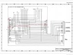
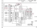
Unit can be jumped at starter relay, but will not start at bush button, Also no lights at Alllison display panel. The head lights work horn works?I have 24 and 12 volts in fuse panel as well. so when I opened up VIM the fuses both have 24 volts. When you plug in main fuse I see cats eyes on display for split second then I hear #3 clicks in VIM relays then nothing?? Crazy thing is when I check from ground post at fuse panel to the 12 volt post or 24 volt post my multi meter reads good. if I check battery ground to ground in fuse panel they are not common ?? what the heck? Is ground on battery should be same as ground at fuse panel right?? Another thing, there is a ground wire from harness off terminal behind Allison selector. when I check resistance from there to ground at fuse panel it reads 0.00 ohms and thats good, but as soon as I turn the green power switch on I get 19 ohms. both ends of my meter are touching frame nothing should effect the resistance to a ground 4 feet away. So I grabbed a jumper cable and clamped it to ground on battery to a bare spot on and still no start. Im a John Deere mechanic and need to bang my head on something. Itook my spare tire off so I can get my head wrapped around a power junction that I found behind cab. I followed battery cables and thats where I'm at now. Im not sure how that unit works but maybe thats part of my issue. I tried going through the M1078 TM for no lights at Transmission display, but the schematic is wrong and my VIM has more than 16 pins on the big one (3 rows not 2 rows). So I am in need for schematic for A0 M1079 1994 model or diagnostic procedure. If anyone has any idea please let me know Thanks so much!
 

Suprman

Well-known member
Supporting Vendor
6,833
646
113
Location
Stratford/Connecticut
If the trans control isn’t functional it will prevent crank at the dash push button. M1078 and M1078 first gen trucks will be the same manual. There is only one Vim used in these series of truck.
 

ou812

New member
12
0
0
Location
lake country
I found it on this sight M1078 there was 8 of them. It was third one down. TM M1078 listed f40 WTECH transmission push button selector does not illuminate. .... so I followed steps the fuse 43 and 79 check was the same, but once it got deeper they have different pin outs on the VIM they show a 32 pin and it has two rows mine has three. anyhow power is there but this ground differences is not making sense.the ground that goes to frame shows open line on multi meter. But yet all lights work and I can bridge the start relay so I know dang well the unit is grounding for those circuits.

If the trans control isn’t functional it will prevent crank at the dash push button. M1078 and M1078 first gen trucks will be the same manual. There is only one Vim used in these series of truck.
 

coachgeo

Well-known member
4,955
3,325
113
Location
North of Cincy OH
on rare occasion a transmission got updated too a wtechIII which may be why things are different than the manual you are looking at.

search in here for WtechIII and read thru some to see if that is what you have. What engine do you have?
 

ou812

New member
12
0
0
Location
lake country
on rare occasion a transmission got updated too a wtechIII which may be why things are different than the manual you are looking at.

search in here for WtechIII and read thru some to see if that is what you have. What engine do you have?
I have 3116 I think? I paid 1,500 bucks for it. Its in great shape, starts and runs fine. It was driving before? owner died 35 years old. pipe line worker.
 

Ronmar

Well-known member
3,234
6,558
113
Location
Port angeles wa
Behind the passenger kickpanel you will either have a VIM(wtec2) or the trans controller(wtec3). Since you are using the acronym vim, And it has fuses inside I would say you have a wtec2.

if you have power thru those fuses then you either have a bad connection to the trans controller under the shift control or you have a bad trans controller.

the box with connections in behind the spare is the polarity protection device. It is diodes which prevent a incorrect battery connection from damaging the controllers in the cab. 12 and 24 from the battery go to terminals on the PPD(also where the alternator is connected). A second set of 12 and 24 wires go from PPD to the test terminals on the power dist panel. The ground goes from battery thru a shunt near the PPD and on to the starter neg terminal. From there a ground strap ties starter neg to the drivers frame rail. Passenger frame rail connects up to the cab floor behind the passenger grill. Inside the cab another strap runs up tot he ground tp in the power panel. If you get 12 and 24 measured to the ground test point, y0u have a path back to batt neg.

an ohmmeter uses a small current to measure resistance. If the two ground points you are measuring across the dash go to a slightly different potential when energized, the meter would react to this by indicating a different inaccurate resistance...

at any rate, until the trans controller and display energize and in turn energize the neutral start relay in the vim, the pushbutton isn't going to crank the engine...
 

ou812

New member
12
0
0
Location
lake country
Thanks Ronmar

If I turn off green switch, then I check from battery neg to neg at power panel they should have common reading with between 0.00-1 ohm correct?. Sounds like I have a bad Wtec2 trans controller. Where and how much?? I still would love a proper schematic or diagnosis on this wtec2, your right I think the one on this site is Wtec3. I lowered the spare tire and the top connector has a bit of corrosion below that theres two positives that go to alternator, and then one more below those? I just wanted to make sure I have good ground. All lights, heater, horn all work. Yes I have power to both fuses. Its the neutral relay that clicks on and off. Is it common for these controllers to go? this unit is only showing 8000 miles why so many issues. I found two bad contacts in power panel related to lights as well, but still not moving. Thanks very much for your help. You have helped me before, but I jus learning how to navigate this site ? you know your stuff.
 

Ronmar

Well-known member
3,234
6,558
113
Location
Port angeles wa
Yes, batt neg to the ground tp in the PDP should be pretty low resistance. If all the lights are working and you get 12 and 24 at the test points the ground has to be there and it is probably OK

The polarity box has 6 wires connected to its 4 terminals. 2 from the battery, 2 from the alt and 2 running to the PDP. The alt and battery cables connect to the same terminals on the polarity box, the other 2 wires to the PDP connect to the remaining 2 terminals. If you have 12 and 24 at the pdp test points with the main switch off and on(circuits loaded) then the polarity box and connections are probably OK.

The manuals for the 1078 up in the manuals section posted by Ptracey are the correct ones. They also show wiring for the wtec2 and 3 in there as they both came in the A0 trucks(wtec3 started sometime in 98 ). There is a copy of the schematics in the back of each of the 20 series manuals(20-1 thru 20-5).

i would start with the “engine does not crank” troubleshooting in the electrical troubleshooting section found in the 20-1 manual page 2-154. Since you can bypass and jump the starter directly you can rule out a few of the possible causes, but I would recommend you still go page by page and read thru all the details. You will note that listed among the possible causes are wtec2 and 3 causes. The procedures listed will help you eliminate each possible cause.
 

ou812

New member
12
0
0
Location
lake country
I went through and found proper diagnostics for wtec2 not illuminating. It asks to check Vim J1 and J2 which I did. They ask for 12 volt reading at those points and mine is 24 volt vim? Also someone has power from fuse panel CB20 not CB35 like it says! So regardless I had voltage so I kept going. I bridged 12 volts to J1and two and same clicking three times no display. I should have checked amps while testing I forgot. The truck is -12 and 40 miles away at another property. So moving on! The diagnostics then asks to check C1 24 volts was good there. Next step was continuity at K1 and K2 ( batteries disconnected and testing unplugged. It was good. Step 4 I think has error they ask for continuity between J1 and R1, they state if continuity is NOT present go to step 12. I did that and all step 12 is, is making sure main power fuse is good. If fuse is good they say to change WTEC 2 VIM? So I pulled the vim apart a checked circuit board I don’t see and issues no loose solder or burnt spots. I would love a proper wiring diagram so I can back prob this stuff.
Q: why can I not give the ecu direct power to verify! Does the push button ecu get power through R1 and R2. Let me know if you can help I’m not convinced it’s the VIM. This VIM looks simple I should be able to bypass something. Thanks for all the help.
 

Ronmar

Well-known member
3,234
6,558
113
Location
Port angeles wa
I went through and found proper diagnostics for wtec2 not illuminating. It asks to check Vim J1 and J2 which I did. They ask for 12 volt reading at those points and mine is 24 volt vim? Also someone has power from fuse panel CB20 not CB35 like it says! So regardless I had voltage so I kept going. I bridged 12 volts to J1and two and same clicking three times no display. I should have checked amps while testing I forgot. The truck is -12 and 40 miles away at another property. So moving on! The diagnostics then asks to check C1 24 volts was good there. Next step was continuity at K1 and K2 ( batteries disconnected and testing unplugged. It was good. Step 4 I think has error they ask for continuity between J1 and R1, they state if continuity is NOT present go to step 12. I did that and all step 12 is, is making sure main power fuse is good. If fuse is good they say to change WTEC 2 VIM? So I pulled the vim apart a checked circuit board I don’t see and issues no loose solder or burnt spots. I would love a proper wiring diagram so I can back prob this stuff.
Q: why can I not give the ecu direct power to verify! Does the push button ecu get power through R1 and R2. Let me know if you can help I’m not convinced it’s the VIM. This VIM looks simple I should be able to bypass something. Thanks for all the help.
The VIM receives both 12 and 24V from CB21, 35 and 79 either directly or via Terminal Board 1. TB1 is broken into sections and is used to distribute 12 or 24V. Anytime you see TB1 it means DC power. TB2 is connected to the ground buss in the PDP so anytime you see TB2 it means ground.

Where is this procedure you are using? The diagram I am looking at does not show an R1 or R2 associated with the VIM. A general wiring pass-thru diagram for the VIM can be found on foldout 21 of 34 of the wiring diagram.

I believe the main power comes from CB79 via TB1-60 to PX33-C1 on the VIM. It goes thru a fuse in the VIM to P116-F1 and on to the trans controller...
 

ou812

New member
12
0
0
Location
lake country
The VIM receives both 12 and 24V from CB21, 35 and 79 either directly or via Terminal Board 1. TB1 is broken into sections and is used to distribute 12 or 24V. Anytime you see TB1 it means DC power. TB2 is connected to the ground buss in the PDP so anytime you see TB2 it means ground.

Where is this procedure you are using? The diagram I am looking at does not show an R1 or R2 associated with the VIM. A general wiring pass-thru diagram for the VIM can be found on foldout 21 of 34 of the wiring diagram.

I believe the main power comes from CB79 via TB1-60 to PX33-C1 on the VIM. It goes thru a fuse in the VIM to P116-F1 and on to the trans controller...
I got it out of the manual by Quincy page 2-1482.16 , I think it was in second one down there is a section in there that reads “WTEC 2 ecu pushbutton shift selector does not illuminate” so I went through that. Says disconnect P116 from Vim, then check ohms at J1 to R1 and states if continuity is not present go to step 12. Step 12 is just checking fuse.

I have power from CB79 but I also trace the power wires from J1 and J2 from vim and they tied those two white wires into one and I can see someone butt connected into a wire coming from the radio CB20 fuse?. It must have worked for them cause it was driving before I got it. Do you know what wires to power up to ecu selector pad ( my ecu is part of push pad) if I use a 9 volt battery and power up the ecu? I just what to make sure, I like to verify them directing me to change VIM. I could not find a proper schematic showing all the wires into the ecu. I checked on line and all I get is WTEC 3 stuff. I should have checked the amperage while I was there cause I could have corrosion somewhere and still show good voltage! I know how to do voltage drops and can figure it out, but they need to show more than just a connector going to touch pad like the one in the end of the Manuals. Thanks for the TB1 info. You can see in in the diagram in back they show the push button selector with two wires going to it ( no details) the VIM in the back does show more. Next time I’m there I’ll go through the engine will not start steps. Thanks
 

NDT

Well-known member
Steel Soldiers Supporter
10,145
5,806
113
Location
Camp Wood/LC, TX
See if this manual can help you. Remember to send your ECU to transmissioninstruments.com for diagnosis and repair if need be.
 

Attachments

Ronmar

Well-known member
3,234
6,558
113
Location
Port angeles wa
I got it out of the manual by Quincy page 2-1482.16
don't know what that is, is it written for the installation used in the FMTV? Got a link so we are on the same page? They use this trans in a lot of vehicles with a lot of different configurations. Unless that manual is specific for this vehicle its troubleshooting may not be applicable... The manual from Allison that NDT posted is a great reference, but again you need the specific LMTV info to make use of it. All the info you need is in the LMTV service manuals, If you are using something else it may be sending you on a wild goose chase.

I believe the power coming to the VIM on J1 and J2 of PX33 is used/switched by the controller to provide control functions like powering the Neutral Start(NS)relay. I am pretty sure the power used to energize the controller comes in on PX33-c1 and exits P116-F1(it is wire number 146, seen on foldout 21) From there it runs thru the dash harness to J115 pin 12 at the controller in the dashboard. This is seen on foldout 18 of 34 the location on the sheet is D-159 for J116 and D-154 for J115 you can see wire 146 going between these 2 connectors.

All the LMTV specific info is in the service manuals so I would highly suggest you use those. You don't need to go any farther than J115 at the controller. If you have 24V at J115 pin 12, the only unanswered question is wether that voltage is still there/adequate under load. So with J115 connected to the controller you need to probe the backside of pin 12 on the connector and see if your 24V is still 24V when the switch is turned on and it is trying to power the controller. If so your controller is probably at fault.

If the voltage drops severely(bad/high resistance connection/wire)you need to sample back thru the circuit to find where the voltage doesn't drop off...
 
Last edited:

MrMikey4026

Well-known member
281
416
63
Location
Eatonville Washington
I have a friend whose WTEC2 was acting the same way. We put in the TCU/keypad from mine and it worked. I took the ECU to my electronics tech at work for a check up. He found 6 bad micro capacitors in the power supply, he replaced them with the more durable can type capacitors and hot glued them to the board to prevent breakage of the wire legs. It cost about four dollars in parts, it works like a champ now. He said the micro capacitors are prone to failure at high rates. I am going to have him replace mine also.
 

coachgeo

Well-known member
4,955
3,325
113
Location
North of Cincy OH
I have a friend whose WTEC2 was acting the same way. We put in the TCU/keypad from mine and it worked. I took the ECU to my electronics tech at work for a check up. He found 6 bad micro capacitors in the power supply, he replaced them with the more durable can type capacitors and hot glued them to the board to prevent breakage of the wire legs. It cost about four dollars in parts, it works like a champ now. He said the micro capacitors are prone to failure at high rates. I am going to have him replace mine also.
have him please do video and/or pictures of the micro capacitors mentioned (where they are on circuit board and where their soder locations are please. Plus part numbers needed to replace them. MUCHO APRECIATO in advance to you and he for doing this!!!
 

MrMikey4026

Well-known member
281
416
63
Location
Eatonville Washington
have him please do video and/or pictures of the micro capacitors mentioned (where they are on circuit board and where their soder locations are please. Plus part numbers needed to replace them. MUCHO APRECIATO in advance to you and he for doing this!!!
When we update mine, we will make a short video with instructions. It is not for the inexperienced or faint of heart, the controller is built kind of like a sandwich with vertical circuit boards between the slices of bread. It requires complete disassembly to get at the problem capacitors.
Mike
 
Top
AdBlock Detected

We get it, advertisements are annoying!

Sure, ad-blocking software does a great job at blocking ads, but it also blocks useful features of our website like our supporting vendors. Their ads help keep Steel Soldiers going. Please consider disabling your ad blockers for the site. Thanks!

I've Disabled AdBlock
No Thanks