• Steel Soldiers now has a few new forums, read more about it at: New Munitions Forums!

  • Microsoft MSN, Live, Hotmail, Outlook email users may not be receiving emails. We are working to resolve this issue. Please add support@steelsoldiers.com to your trusted contacts.


M211 crew cab crusade

snowyrivers

Member
138
1
18
Location
Newberg Oregon
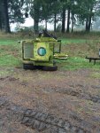
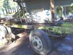
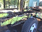
Will keep new stuff coming as it happens.

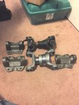
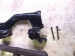
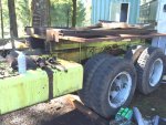
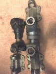
The new drive shaft parts I scored off ebay are enroute.

Could not believe getting a $600 shaft for $100
 
Last edited:

snowyrivers

Member
138
1
18
Location
Newberg Oregon
Yup

The cost for the 1410 shorty shaft with joints was $1000 list and $587.06 my cost

Popped it into ebay and one showed up with an opening bid of $100
Nobody else bid on it and I scored it for opening bid

$15 shipping

$115 against $587.06
 

Attachments

snowyrivers

Member
138
1
18
Location
Newberg Oregon
I also dug up the flange yoke the will mate to the input of the original 6x6 4 bolt flange.

We still need a 1410 output yoke for the 205

Found one, just waiting for the auction to get far closer to ending before jumping in.

They are not a real spendy part

May go with a 1410 bolt flange on the 205

Stronger and will be easier to get the shaft in and out if need be.

Fun stuff
 

snowyrivers

Member
138
1
18
Location
Newberg Oregon
Not much got done yesterday except a trip to Harbor Freight to get a material support stand to go with the Jet cutoff saw.

The shorty tail shaft housing I ordered up off ebay showed up near dark last night.

Great deal to get one in top shape CHEAP

We want to keep the length of the ENGINE, TH400 AND THE NP205 as short as possible.
 

snowyrivers

Member
138
1
18
Location
Newberg Oregon
The little shorty 1410 drive shaft showed up yesterday afternoon.

Sweeeeeet

Decided after looking at the size of it ( spline shaft diameter) that it is better suited to being located between the TH400 and the NP205 than back buckled up to the 6x case.

I DO NOT want those shorty shafts ending up being THE FUSE

Decided to step up to the plate and go with a 1550 series shorty in that location.

Soooooooooooooo.

Downloaded the Spicer tech book and checked out the part numbers and prices.

The Shorty 1550 series shaft complete was gonna be a shade over $1000 when purchased new as an assembly (More depending on the vendor)

Took all the individual part numbers and went to ebay.

Yeah buddy.

Immediately found the Slip yoke and the spline'd yoke (Exact part numbers)

The pair were $130 with free shipping (New old stock)

Next came the flange yokes for each end.

Another great score at $56 for the pair

Still need the u joints but they are a standard 1550 joint and generally can be scored around $30 each on ebay.

Soooooooooo

For under $250 we are good to go.

Still need new flanges for the 205 for the input and outputs

Using the bolt flange type will keep life easy and the assembly strong and maintenance/disassembly very easy from either the top down through the floor access or the bottom up (LAYING IN THE MUD) ARRRRRRGH

Here is a piccy of the 1410 Shorty shaft and the shorty extension housing recently scored for the project.

Lotsa hours spent behind the terminal and with paper, pencil and calculator while looking over parts spec sheets.

The numbers all crunch good on the shorty drive shaft choioces.

The 1410 shorty is rated at an upper limit of 1600 ft lb of torque and this leaves plenty of safety margin in the slot between the 400 and the 205.

The big 1550 shorty can handle up to 4000 ft lb and this is way more than we should ever be able to exert between the 205 and the 6x case (205 down in the BUSINESS HOLE)

Real happy how this is coming together.

All off the shelf parts that COULD be replaced if need be.

May take some snooping to find a bolt flange type slip yoke for the TH400, but not worried as we could use a standard 1410 yoke there.

Really wanting bolt flanges all the way on this thing as they are easier to work on and much stronger.

Just waiting for the little brown truck now
 

Attachments

snowyrivers

Member
138
1
18
Location
Newberg Oregon
Parts starting to show up now.

Got more drive shaft stuff yesterday and more should be here today.

More ordered.

Really sucks to have to get this stuff one little piece at a time, but when the prices are good ya run with it.
 

snowyrivers

Member
138
1
18
Location
Newberg Oregon
Actually the stuff came POSTAL :naner: 
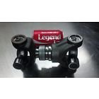
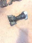
second day and the freight was part of the purchase price.

Don't have the joints for the bigggun and still missing one flange for the little one.

Gotta be cheap or this cat ain't pouncing on it.

PIX PIX PIX

The 1550 set up is heavy... about 30 pounds when assembled.

Should resist being broken
 

Attachments

snowyrivers

Member
138
1
18
Location
Newberg Oregon
Got busy and installed the one flange we have on the 1410 shortie

Nice having new parts that are clean and rust free to work with.

Still snooping for another flange.

They come in a few different specs (Bolt hole size and spacing and depth from center of u joint bearing to flange face.


I dont want a mismatched mess.

Gotta be the same
 

Attachments

snowyrivers

Member
138
1
18
Location
Newberg Oregon
Located the last items needed to complete the two shafts.

Needed one 1410 flange and two 1550 u joints

Careful cruising on the net scored the big joints for $12.50 each (Spicer no less) and the 1410 flange is coming from a place called "Finditparts"

Prices on components are all over the map price wise and careful shopping can net some great deals.


If all goes well we are going to lift the cab off the old girl tomorrow and get it out of the way.

The next important phase is to get the chassis to DMV and get the title transferred.

The next phase will be to finish clearing the junk off the frame and then we can get after things in a big way.


Yesterday we picked up some stock motor mount bolts for the GM engine mounts and the plan is to hang the engine cross member on the engine and then get some real accurate dimensions from the very front of the fan clutch to points on the cross member to establish references to locate the salvaged bracket in the M211 frame rails.


Once we can get that cross member in the rails we are OFF TO THE RODEO

From this point the engine can sit in the frame, then the TH400 can bolt into the mix.

The original rear tranny cross member is an excellent piece and just needs to be relocated and new holes drilled in the frame and a new mount that works with the TH400 fitted.

At this point life is gonna get interesting.

Now that we have our shorty drive shafts we can accurately calculate the location of the 205 T CASE and then the relocation of the 6x case towards the rear of the chassis.

Drive shaft mods will be needed on all shafts as well.

My "Best guess" at this point in time is that the 6x case is going to be moved rearward approx 18" to facilitate the addition of the 205 and the two shorty shafts.

In the worst case scenario the 6x case can be moved back nearly 2 feet and not hurt anyone's feelings.

If a case of drive line angles comes into the equation we can always stuff in a couple CV joints up at the 6x case.


If this sounds like "Build from the radiator back and sweat the small stuff later" YOU'RE SPOT ON.

The radiator mount up front is/was a nifty set up with a rubber type pad with 2 shoulder bolts and springs retaining the assembly to the frame mount.
This novel design allowed the truck to be twisted like a pretzel and and the radiator frame would be able to flex along with the fenders and the "Propeller" would not eat the fan shroud.

A pair of nifty little arms extended from the original front motor mounts and would contact brackets on the radiator frame if the frame was twisted beyond a certain point.


Getting the radiator mounted back in the original location will take a bit of finesse as the actual cab placement back on the frame (Elevation due to more modern mounts/ GM TRUCK/ BURB BODY MOUNTS)

Likely the vertical height of the radiator will need to be adjusted and the final design on the fan shroud will need to wait until everything is sorted out.

With the terrible torture that these old horses saw and came through standing tall it is obvious that the engineers did a pretty darned good job.
 
Last edited:

snowyrivers

Member
138
1
18
Location
Newberg Oregon
Weather was decent today, so got some tinkering done.

Cleaned up the cross member from the Burb and got it ready to slip into the engine mount cradles on the 6.2.

Gonna take two of us to wiggle that sucker into the cradles and stuff the bolts in.

Once that's done the measuring can begin.

Some pix
 

Attachments

gentrysgarage

Active member
553
118
43
Location
Lost Angels, CA
I am working on getting a frame and axles for my truck, can I get you to take a picture of the frame from the side. And PM it to me? Shippers like pictures it seems
Thanks in Advance
 

snowyrivers

Member
138
1
18
Location
Newberg Oregon
OK TROOPS

Time for some serious drive shaft theory ! ! ! ! !

Yesterday after getting the cross member stuffed onto the 6.2 diesel I started getting some useful measurements to allow the new package to drop into the frame.

After some measuring I went over to the frame and started laying things out, and soon a serious issue loomed up out of the murkiness.

The frame is sitting level and the T case in/out shaft is parallel to to the frame as are the diffy pinions.

So here is where the rub comes . . .

The original centerline of the engine and tranny is at a 5 degree angle in the frame with the rear of the tranny (Output shaft) at the same elevation as the T case input.

(From front of crank to rear of tranny the drop is 5 inbches)

Normally the centerline of engine/tranny is parallel to T Case input shaft centerline and the centerline of the diffy pinion shafts.

Standard practice is that all shafts are parallel and run at different elevations to obtain the desired running angle.

The arrangement in the center shaft (Angle) on the 211 is not this way.

The shafts are not parallel.

Who has scoped this out and actually addressed the issue when doing a re-power.

This is not an insurmountable problem, but I am curious why it was done this way from GM of all people.

My first inclination is to user a real short CV shaft between the tranny and the 205 to kill the angle issue.

Any input here is welcome.
 

snowyrivers

Member
138
1
18
Location
Newberg Oregon
Driveshaft tech 101

Very good stuff from right out of the text book.

I had this same basic stuff in Auto tech school back in 70 and 71

The info I am hoping to stumble on to is the odd ball stuff that was built by major manufactures and that broke all the rules of Driveshaft 101

Obviously the original setup worked fine and had minimal trouble, but these rigs were never designed for highway speeds (55-60 mph)

I have been through 4x4 101 (The hard way as a kid) and broke my share of toys.

I spoke with a major driveline builder locally this morning and discussed this issue in length.

He was pretty much as I am, ahhhhh wtf were they thinking ????


A shorty CV shaft in the equation will fix it up fine.

I had not planned on that in the mix.

Trying to keep the assembly as short as possible.


A real wonder what for sure.

BTW
The article is a great read

Thanks for sharing.
 
Top
AdBlock Detected

We get it, advertisements are annoying!

Sure, ad-blocking software does a great job at blocking ads, but it also blocks useful features of our website like our supporting vendors. Their ads help keep Steel Soldiers going. Please consider disabling your ad blockers for the site. Thanks!

I've Disabled AdBlock
No Thanks