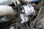
If you have an alternator the regulator should be internal, actually it is on the back of the unit. If an alternator is not charging the voltage that one would get from the output is what the batteries are providing. One simple way to check for output is to see what the alternator is putting out without the batteries hooked up.
NO!!
The battery(ies) act as a filter on the DC circuit, capping electrical switching transients that can easily hit
200 (TWO HUNDRED) volts. Many 24V Electronics do not react well to 200V appearing on their power
feed.
Now maybe the various and sundry M35's effectively have no "electronics" to destroy...
but a bad habit to get into nonetheless.
I have an interesting "Application Note" from Intel on this subject, but offhand don't know how
to "attach" a text document to one of these replies, so I'll try to just dump it inline following
------------------------------------------------------------------------------------------------------
Intel AP-125THE AUTOMOTIVE ENVIRONMENTThe automobile presents an extremely hostile environment for electonicsystems. There are several parts to it:1. Temperature extremes from -40C to +125C (under the hood) or +85C (in the passenger compartment)2. Electromagnetic pulses from the ignition system3. Supply line transients that will knock your socks offOne needs to take a long, careful look at the temperature extremes.The allowable storage temperature range for most Intel MOS chips is-65C to +150C, although some chips have a maximum storage termperaturerating of +125C. In operation (or "under bias," as the data sheets say)the allowable termperature range depends on the product grade, asfollows: Grade Ambient Temperature Min Max Commercial 0 70 Industrial -40 +85 Automotive -40 +110 Military -55 +125The different product grades are actually the same chip, but testedaccording to different standards. Thus, a given commercial-grade chipmight actually pass military temperature requirements, but not havebeen tested for it. (Of course, there are other differences in gradingrequirements having to do with packaging, burn-in, traceability, etc.)In any case, it's apparent that commercial-grade chips can't be usedsafely in automotive applications, not even in the passenger compart-ment, and automotive or military chips are required in under-the-hoodapplications.Ignition noise, CB radios, and that sort of thing are probably the leastof your worries. In a poorly designed system, or in one that has notbeen adequately tested for the automotive environment, this type of EMImight cause a few software upsets, but not destroy chips.The major problem, and the one that seems to come as the biggest sur-prise to most people, is the line transients. Regrettably, the 12V bat-tery is not actually the source of power when the car is running. Thecharging system is, and it's not very clean. the only time the batteryis the real source of power is when the car is first being started,and in that condition the battery terminals may be delivering about5V or 6V. As follows is a brief description of the major idiosyncraciesof the "12V" automotive power line.o An abrupt reduction in the alternator load causes a positive vol- tage transient called "load dump." In a load dump transient the line voltage rises to 20V or 30V in a few microseconds, then decays exponentially with a time constant of about 100 microseconds. Much higher peak voltages and longer decay times have also been reported. The worst case load dump is caused by disconnecting a low battery from the alternator circuit while the alternator is running. Nor- mally, this would happen intermittently when the battery terminal connections are defective.o When the ignition is turned off, as the field excitation decays, the line voltage can go to between -40V and -100V for 100 micro- seconds or more.o Miscellaneous solenoid switching transients can drive the line to + or -200V to 400V for several microseconds.o Mutual coupling between unshielded wires in long harnesses can in- duce 100V and 200V transients in unprotected circuits.What all this adds up to is that people in the business of buildingsystems for automotive applications need a comprehensive testing pro-gram. An SAE guideline which describes the automotive environment isavailable to designers: SAE J1211, "Recommended Environmental Prac-tices for Electronic Equipment Design," 1980 SAE Handbook, Part 1, pp22.90 - 22.96.Some suggestions for protecting circuitry are: A transient suppressoris placed in front of the regulator chip to protect it. Since the risetimes in these transients are not like those in ESD pulses, lead induc-tance is less critical and conventional devices can be used. The regu-lator itself is pretty much of a necessity, since a load dump transientis simply not going to be removed by any conventional LC or RC filter.Special I/O interfacing is also required, because of the need for hightolerance to voltage transients, input noise, input/output isolation,etc. In addition, switches that are being monitored or driven by thesebuffers are usually referenced to chassis ground instead of signalground, and in a car there can be many volts difference between the two.[Several "figures" and graphs are of ASCIIty not shown here; there isone very striking "Figure 25. Transient Created by De-energizing anAir Conditioning Clutch Solenoid" ('scope photo) with an incredible-400V microsecond-sized transient shown. Ye-Ouch!]
------------------------------------------------------------------------------------------------------
Well, that looks hideous, lost all pretenses at formatting. Oh well...I tried.
-RDH