• Steel Soldiers now has a few new forums, read more about it at: New Munitions Forums!

  • Microsoft MSN, Live, Hotmail, Outlook email users may not be receiving emails. We are working to resolve this issue. Please add support@steelsoldiers.com to your trusted contacts.

M35A2 driveline angles - need angle measurements from engine to xfer case

HanksDeuce

Well-known member
1,080
238
63
Location
Prairieville, LA
It seems that I enjoyed taking the factory multi-fuel engine and Spicer 3053A transmission out of the deuce, but I forgot to take a few key measurements before I started the job.

I am looking to see if someone could help me determine the following measurements on a factory deuce:
1) park deuce on level ground

2) Measure the following items:
a. angle of deuce engine - put angle finder on top of engine
b. angle of Spicer 3053A transmission - on top or flat spot on bottom
c. angle of Spicer 3053A output yoke
d. angle of transmission to transfer case driveshaft (aka intermediate shaft)
e. angle of transfer case input yoke
f. angle of transfer case - on top or flat spot on bottom
g. if intermediate shaft is completely horizontal then maybe it is offset to one side of the chassis (favors one frame rail or the other)

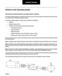
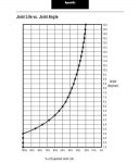
These measurements will help me determine the angle required on the intermediate shaft. My driveline guy down the street recommends needle bearings get at least 2 degrees of angle so they spin in the u-joints. I would like to run my Cummins 6BT between 0-5 degrees down. The freightliner bus that was the donor vehicle for my project had a 5 degree downward angle for the 6BT engine/tranny.

I have attached a picture for reference. Keep in mind the rear diff is now the xfer case in this instance. And that I need the engine angle too. It should be the same as the tranny, but someone may surprise us.

Thanks in advance!
 

Attachments

Last edited:

HanksDeuce

Well-known member
1,080
238
63
Location
Prairieville, LA
Further research led me to a great resource: http://www2.dana.com/pdf/J3311-1-DSSP.pdf‎

Page 8 of the Dana Driveline Installation manual in the link above has been attached for reference.

Current thinking:
1) install Cummins 6BT at zero angle to match xfer case
2) adjust elevation of 6BT to get at least 1 degree of angle in each u-joint on the intermediate shaft between tranny & xfer case

Thoughts/concerns?
 

Attachments

ivbeenrokd

New member
423
1
0
Location
knoxville, tn.
Are you thinking of leaving the t-case at 0? My driveline guy is saying he may want me to change the t-case angle to get it off 0. I'm also thinking he may have said you don't want both angles the same at both ends of the same shaft, I could be wrong about that.
 

HanksDeuce

Well-known member
1,080
238
63
Location
Prairieville, LA
Based on the Dana reference material and other books I found it is highly recommended that whatever you are bolting a driveshaft up to (at either end) must have the same angle.

Example would be if the transfer case output is at 0 degrees (horizontal), then the pinion flange on the axle would need to be at 0 degrees (horizontal) as well. The elevation change between the transfer case and axle pinion would set the u-joint angles. Based on the Dana material the minimum u-joint angles are 1 degree at each end, and they must be within 1 degree of each other. Dana goes on to say that a driveshaft in front of a transfer case needs to have u-joint angles at each end within 0.5 degree of each other.

There are additional requirements listed on the attached chart that correlate u-joint angle to expected life.

I can tell you with the 8" lift my front driveshaft has u-joint angles that are very high. If I drove in 4wd all the time I would probably eat a u-joint up every week. But, the free wheeling hubs help take that burden off the driveshaft and it doesn't turn unless I lock the hubs in.
 

Attachments

Last edited:

ivbeenrokd

New member
423
1
0
Location
knoxville, tn.
Maybe what I'm thinking of relates to a 2 piece driveshaft. The majority of our discussions have been around that since that's what I'm doing. I think the rules are a little different for a 1 piece vs. a 2 piece with a carrier. Either way, I'm no expert on this topic, I'm just going to let him take care of it and tell me what height to put the carrier.
 

mudguppy

New member
1,587
15
0
Location
duncan, sc
If the shaft is a single joint at each end then you want the input/output flange faces to be on the same plane (angle) - e.g. 0 at trans should mean a 0 at the transfer. OR, the input/output flange face angular difference must be shared equally - e.g. 10 deg downward angle of engine/trans compared to 0 deg of transfer input means shaft should see 5 deg at each end. If the input/output flanges cannot be on the same plane and you cannot split the angular difference equally, then you would utilize a double-cardan joint at one end - the other end of the shaft should be aligned to meet the flange face at 0 degree (perpendicular) - this can be viewed by the double-cardan (CV) joint installation diagram from the same source as the document you posted in post 3. These are all efforts to eliminate phase vibration.

Also, as we discussed, a u-joint needs to have some angle built into it for reliability - if there is no angular changes, then the rolling elements in the u-joint will not circulate lube well-enough and will soon eat into the raceways in the cups. You need at least 2 degrees** to get sufficient travel of the rolling elements of each u-joint.

Since we're dealing with very short shafts, little offset is needed to achieve this angle - this can be in any direction, too.


**btw - the source of my statement of 2 degrees required is from reliability engineering courses. IMO, the statement in the document provided of 1 degree is for a driveshaft on a suspension component that will see changes in operation due to suspension cycling. Since we're talking about the jack shaft, these are essentially 'fixed shafts' - a shaft that spends it's service life at a constant angle will need more than 1 degree. just my $0.02.
 
Last edited:

mudguppy

New member
1,587
15
0
Location
duncan, sc
... Dana goes on to say that a driveshaft in front of a transfer case needs to have u-joint angles at each end within 0.5 degree of each other. ...
Of course they do!!! This is guidance for optimizing component service life - Dana doesn't build vehicles. But they can definitely provide guidance to help OE designers keep components happy so they make it through the x00,000 mile warranty before needing servicing. And so if your joint is installed with 15 deg angular operation, you should only see a service life of approximately 20% of that x00,000 miles... what would that be - 20k? 30k? 40k??? We simply aren't putting on that many miles.

Did you know that, also according to bearing manufacturers, rolling element bearings should have an approximate service life of at least 22.8 years... of continuous use? But, lots of things go into that: proper installment techniques, proper fitment (huge topic!), service conditions (avg load, peak load, rpm, temp, etc.) and then lubrication (type and quantity, an even bigger topic!). Did you know that bearings, per type, size, and service, require a near-constant replenishment of lubrication? There are tables from the manufacturer that specify exact volumes of grease consumed by the bearing... then its our job to figure out how to replenish it continually (weekly, bi-monthly, monthly, all with varying impacts to predicted service life). Do you think 'hand-packing' wheel bearings annually meets this intent? Did you know that there is a maximum operating temp for both lube and bearings? Does anyone think that wheel bearings can go for 22 years of continuous operation (800rpm, 24hrs/day), no matter how closely you follow the TM?

Here's another fun fact: did you know that, for every 18 deg of operating temperature over 140 deg F, that the service life of lubrication gets cut by 50%? Did you know there's a similar scale for bearings, and starts as low as 160 deg???

What the heck is my point? This: be careful with the manufacture's guidance - it can drive you crazy and may not be worth all the headache trying to achieve an ideal world. While it is great guidance to follow, the reality is that so many other factors will determine the service life of components long before 1 or 2 (or even 5) degrees of operating angles. Installation techniques and lubrication will cause significantly more trouble than minor u-joint angle.

Sorry - not a rant or pointed at you, Hank - just real-world vs 'theory' FYI with regard to machine design and reliability that I think everyone should be aware of.

And I was bored at work...
 
Last edited:
Top