• Steel Soldiers now has a few new forums, read more about it at: New Munitions Forums!

  • Microsoft MSN, Live, Hotmail, Outlook email users may not be receiving emails. We are working to resolve this issue. Please add support@steelsoldiers.com to your trusted contacts.


M35A3 dual fuel tank setup

Sgt Jiggins

Potato Peeler
Steel Soldiers Supporter
431
204
43
Location
Lynchburg, VA
Hello,

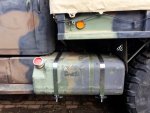
Just finished mounting 395/85R20s and an electric fuel pump on the M35A3. Which left me without a reasonable way of putting the spare in the original location. But... plenty of room to hang a 2nd fuel tank. Anyone done this?

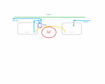
I can see taking the return line down the driver's side frame rail and using that as input to the 2nd tank. But hooking the 2 tanks together? Bernoulli says they'd both be at the same level as the lowest situated common connection... Eg, if I run a hose from the inside-bottom on the driver's to the inside-bottom on the passenger side both tanks would fill and then drain to that low level.

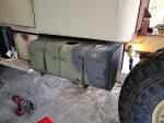
I guess I'd just need to find/make a clear path to run the intermediate hose and brush up on my aluminum welding skills.

Thoughts/input?

Thanks,
SJ/JD
 

Sgt Jiggins

Potato Peeler
Steel Soldiers Supporter
431
204
43
Location
Lynchburg, VA
I’ve been trying to sort out how to plumb a dual tank diesel system and figured somebody on here (thanks Montaillou) has done this too. It's more or less of an open/non-pressurized fluid system. Input (diesel) is periodically added to the system (raising the fluid level) as the engine consumes it (dropping the fluid level). Pressure is only on the output side after the pump.

Below is a very crude drawing of what I’m trying to work toward. Presently all I have is tank 1, with both input and output from that one tank, via the 1 pump moving the fluid. I’d like to get a point where I can put fuel into tank 1 (via a filler neck) and have the fluid levels balance across both tanks. The input and output as you see them below: output is to the engine. Input is return from the injector pump (how it accounts for varying levels of fluid consumption).

I think the principle is Bernoulli’s? My question though… given the orange line, what happens to the fluid level in each tank as the overall volume of fluid in the tank system leads the balanced level to drop below the peak of the orange conduit? Will the tanks still equalize? Or will it start to fill tank 2 and only drop over to tank 1 as it crosses the peak of that orange conduit?

The “no go zone” is where things like driveshafts live. Would love to use existing top-side fittings (2 per tank already exist) if possible but can weld others on as needed. The tanks are 50 gallons each. I’m aiming for as close to 100g of capacity as possible.

Cheers,
SJ
 

Attachments

montaillou

Well-known member
Steel Soldiers Supporter
789
777
93
Location
W.WA
My second tank isn't fully hooked up. I'm actually waiting to install my 3rd and maybe 4th tank and do them all at once. My plans are to keep them all separate from each other. This gives me the option of using different fuels also, if one tank gets holed (or that fuel line does) chances are some of the other tanks will still be functional.

And just to go the extra distance, I'm surrounding one tank with class 3 ballistic fiberglass.
 

Sgt Jiggins

Potato Peeler
Steel Soldiers Supporter
431
204
43
Location
Lynchburg, VA
My second tank isn't fully hooked up. I'm actually waiting to install my 3rd and maybe 4th tank and do them all at once. My plans are to keep them all separate from each other. This gives me the option of using different fuels also, if one tank gets holed (or that fuel line does) chances are some of the other tanks will still be functional.

And just to go the extra distance, I'm surrounding one tank with class 3 ballistic fiberglass.
Wow that's a lot of capacity. Where are you looking to hang 3&4? How are you going to switch them?
 

Sgt Jiggins

Potato Peeler
Steel Soldiers Supporter
431
204
43
Location
Lynchburg, VA
Why not add a second pump and a check valve?
Fair enough. I guess it doesn't hurt them to run dry when the system gets low on fuel. I could put a level gauge in the 2nd tank and have a relay stop the 2nd pump when it got too low...

Anybody have any suggestions for a decent level gauge?
 

montaillou

Well-known member
Steel Soldiers Supporter
789
777
93
Location
W.WA
Where are you looking to hang 3&4?
My plan is to put a custom built camper in the bed with a 9" sub floor. This sub floor will contain a lot of mechanicals for the camper including a custom built fuel cell. It might be too unwieldy to have a single tank so I've been thinking 2 will be easier to install. The tank pictured a few posts above is from a 5 ton with about 70 gal capacity - the tool box & step had to be slightly shortened to make it fit. I want to get up to around 200 gal. total. However, I have some budget considerations and if this is too expensive it might be less, but there will be a 3rd tank at least.

As to controlling them, I'll need an external pump on the 2nd and 3rd+ tanks to simulate what the in-tank pump does on the original tank, the lines will converge at some point to a electric selector valve (I'm still looking at this and whether to include a mixing valve). Each tank will have an individual sender and switch in the cab.

I will be contacting a local fabricator this week to get the ball rolling on the tank.

Here's a general layout that I'm working on, each square is 2 inches on a side:
 

Attachments

Last edited:

montaillou

Well-known member
Steel Soldiers Supporter
789
777
93
Location
W.WA
Mostly. Batteries are around 7.5" tall with posts. They'll be resting on a rubber pad, with sides and the top free. When I spoke to the fabricator for the tank he said he thought he could make a fuel cell 7" high, if it needs to be taller, then the sub-floor will be taller. The water tanks I've found are less than 6" high, the grey water tank is 7.5". I think anything else I put in there I should be able to find that'll fit in the space. There are other things that will be down there, but the big stuff determines the layout. For instance, most of the plumbing and wiring will run down there and come up through the walls where I need it. There will be water sensors on the floor in case one of the water tanks leak.

The sub-floor will be an enclosed box - I want a little heat from the camper to keep water from freezing. I'm thinking 1/2" x 2" rectangular tube to support the floor with hatches everywhere so I can get to any part of the sub-floor. This is one reason I'm thinking of making the fuel tank there smaller or into 2 tanks. As one tank, if it ever needs to come out it'll be a pain.
 
Last edited:

Grummanflyer

New member
20
11
3
Location
milton, ky
25 years ago when I worked on big trucks, they had a crossover line on the bottom of each tank that kept the levels in each tank equal. The line only needs to be big enough to satisfy the engine requirements. It would not allow for single point filling unless it was pretty large. The line was supported by a stringer that was connected to the tank mounting saddle. It's plenty low enough to miss driveshafts,etc. These used to get packed with ice in the winter time causing the fuel to gel and the truck would run out of fuel on the main tank with plenty on the other side. If you cannot violate the "no go" rule then this option will not work and of course would necessitate a fitting in the bottom of each tank.
 
Last edited:

Jeepsinker

Well-known member
5,341
328
83
Location
Dry Creek, Louisiana
If it was just a two tank system I'd suggest using the fuel tank selector valve from an M936 or M931 truck and just mounting the fuel pump on the upstream side of it so it can pull fuel.
You could do the same for the other two tanks and simply plumb the output to fill the saddle tanks. Plumb the lister tanks together so you can use the single output side of the valve as the input instead, leaving two outputs (one for each saddle tank).
 

Modiconman

Member
33
12
8
Location
Richmond, VA
I added a second tank on the drivers side where the tool kit was. I used a regular tank with the in tank pump. I connected the two via a set of check valves to the main fuel line. I set up a motorized valve to switch the return lines properly. With one switch in the cab, I20190817_165233.jpg can switch between the two tanks at will.
 

Attachments

Modiconman

Member
33
12
8
Location
Richmond, VA
This is where I got most of my inspiration from:
 

montaillou

Well-known member
Steel Soldiers Supporter
789
777
93
Location
W.WA
very common to aircraft
I've looked at aircraft parts before, they tend to be super expensive because they're made for...aircraft. While I can appreciate a well made part, it's just more than I need and I don't need the added expense.
 
Top
AdBlock Detected

We get it, advertisements are annoying!

Sure, ad-blocking software does a great job at blocking ads, but it also blocks useful features of our website like our supporting vendors. Their ads help keep Steel Soldiers going. Please consider disabling your ad blockers for the site. Thanks!

I've Disabled AdBlock
No Thanks