• Steel Soldiers now has a few new forums, read more about it at: New Munitions Forums!

  • Microsoft MSN, Live, Hotmail, Outlook email users may not be receiving emails. We are working to resolve this issue. Please add support@steelsoldiers.com to your trusted contacts.


M51 Sprag Replacement

M51clueless

Member
38
29
18
Location
Tennessee
Need some help

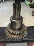
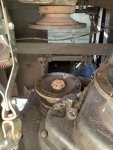
I cannot get the upper shaft to slide out.

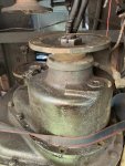
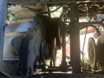
Have not found the step by step in the tm for how to take the nose piece off the front to the transfer case ,

what I have done is
remove the front driveshaft
disconnect the air lines
remove the driveshaft between the transmission and transfer case.
disconnect the speedometer cable

worked real hard to get the upper shaft to move , was only able to get 1/4 inch or so.
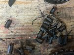
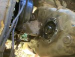
finally saw the cover on the back side of the transfer case, took it off and found a snap ring, was sure I had it figured out but sill no luck getting the upper shaft to budge
 

Attachments

gringeltaube

Staff Member
Super Moderator
Moderator
Steel Soldiers Supporter
6,879
2,254
113
Location
Montevideo/Uruguay
... upper shaft to slide out
Why? If you mean the input shaft itself, it has nothing to do with removing the front output assembly in order to get access to the sprag unit.
Unlike its smaller cousin (the M35s T-case) you may have to pull the input companion flange (4) first, before that housing can come off.
(I've never worked on a 5-ton TC so I'm not 100% sure)

This may help....
1602888071438.png
1602887794192.png
 

M51clueless

Member
38
29
18
Location
Tennessee
Did find the brake down of the transfer case in the tm. form what I am reading looks like that upper shaft stays in place, I need to pull the companion flange, then the nose piece will have the clearance necessary to slide off.

course if you have done the job would love any pointers!
thanks
 

M51clueless

Member
38
29
18
Location
Tennessee
Why? If you mean the input shaft itself, it has nothing to do with removing the front output assembly in order to get access to the sprag unit.
Unlike its smaller cousin (the M35s T-case) you may have to pull the input companion flange (4) first, before that housing can come off.
(I've never worked on a 5-ton TC so I'm not 100% sure)

This may help....
View attachment 815279
View attachment 815278
Thanks I did find that and yes looks like I was trying to do it wrong, I will re-secure the upper retaining ring , get the snap ring back on then pull the companion flange. Hopefully will be able to pull the nose off then.
 

M51clueless

Member
38
29
18
Location
Tennessee
So made some progress,
finally Ready to remove the nose piece
I have a concern,
with the noise piece tight to the transfer case , the bottom companion flange turns freely
As I start to separate the noise piece the companion flange binds.
Is it ok to continue to force the noise piece off?
 

Lovetofix

Member
87
62
18
Location
Morrison,TN
I did that this year as well. The inner end of the front output shaft inserts into the end of the rear output shaft about 2 inches. In other words, the front shaft slides into the hollow end of the rear shaft. Any angle of the “front nose” as you called it, relative to the main case, will make it bind. Just keep tightening the jacking bolts and help it off as straight as possible with a pry bar. Once you get it off the dowels it will come right off. Be careful not to let it fall on you!
An alternate way to take it off is to remove the output flange and leave the shaft hanging in the transfer case while you take the housing off. It is a lot lighter that way if you are trying to do it by yourself.


Here is what you are trying to get to.


M51clueless

Member
38
29
18
Location
Tennessee
Thanks for the reply,

I had reviewed the tm and got after it and it slid right off.
Now the next drama, have dismantled the sprag and removed the 2 snap rings.
From what I read the next step is to press the shaft out.
using my new 12ton press it just laughed at me .

Apparently I either am doing it wrong or I need a more mondo press

any thoughts ?
 

Attachments

M51clueless

Member
38
29
18
Location
Tennessee
We’ll heat did the trick, sounded like a cannon going off . And the new sprag assembly pressed right on.

Now back to some above average suffering trying to get the unit back on the transfer case.
same as before ,the front companion flange was binding as I was removing the noise piece.
It is binding as I am trying to install it.
was able to get it within 1/2 inch of the transfer case, was using bolts to draw the nose piece up.
Had 8 bolts started, had them even as I drew it up. Got to a point were didn’t want torque them any tighter.

Out of ideas

Tell me what I am doing wrong
 

Lovetofix

Member
87
62
18
Location
Morrison,TN
Did you remove the speedometer assembly?
That sticks in about 1/2” and may not be lined up right.
Is the shift fork shaft moving freely?


Sent from my iPhone using Tapatalk
 

M51clueless

Member
38
29
18
Location
Tennessee
No, I did not remove it . On the tm it showed installing it last. the tap that protrudes into the case is out of the housing is out but housing is in place. , I’ll take the speedometer housing off in the morning and give that a try.

lf that doesn’t work my next idea is to take the whole noise piece off ,take the companion flange off, then install the sprag assembly by itself, than slide the housing on.

Thanks for the suggestion, I am loosing all my humor on this project, Monday will be day 4 , should have taken 4 hours (well maybe 2 days)

what’s that line from Galaxy Quest “Never give up, Never surrender! “
 

Ajax MD

Well-known member
1,571
1,420
113
Location
Mayo, MD
No, I did not remove it . On the tm it showed installing it last. the tap that protrudes into the case is out of the housing is out but housing is in place. , I’ll take the speedometer housing off in the morning and give that a try.

lf that doesn’t work my next idea is to take the whole noise piece off ,take the companion flange off, then install the sprag assembly by itself, than slide the housing on.

Thanks for the suggestion, I am loosing all my humor on this project, Monday will be day 4 , should have taken 4 hours (well maybe 2 days)

what’s that line from Galaxy Quest “Never give up, Never surrender! “
This is really educational. Keep at it.

The output bearings for the front and rear driveshafts were totally shot on my t-case so I ended up replacing the entire unit with a rebuilt t-case. I've wanted to see the guts of this thing.
 

M51clueless

Member
38
29
18
Location
Tennessee
Well to update, another 12hr day on this project, got to say I think I have an understanding of a sprag now.

took a couple of steps back today before working it out, I managed to install the main gear upside down , figured that out after not being able to draw the housing up all the way, or so I thought.

Had to disassemble the shaft assembly, was having trouble getting it apart and took a snap ring holding half of the sprag in place, that did two things, it allowed me to slide the outer collar off, but the sprag separated just enough that one of the springs fall out of place.

Hour or so later, got a technique figured out and all the pieces back together.

Turns out the shaft was deformed enough that it made it difficult to pull off and down right impossible to re-install,

I was slow to figure that out, was not until I had given up on installing the unit as a whole and taken Lovetofix suggestion that I could install the gear assembly by itself cutting the weight down making it easier to handle.

After putting the gear assembly onto the transfer case, I could see that it was the shaft that was binding, I had noticed that the shaft had some wear and had used a grinder to smooth it some, apparently not enough though

I got more aggressive with the grinder and that did the trick!

After that the sprag assembly slid right on, I got most of it back together, will install drive shafts tomorrow and should finish.

Got a few pictures of it 5A06D934-EB60-429E-A59D-14A61D703B50.jpeg5A06D934-EB60-429E-A59D-14A61D703B50.jpeg5A06D934-EB60-429E-A59D-14A61D703B50.jpegAA74C2A1-A576-45D5-A36D-32AA7FF33644.jpeg03034B5A-7B1F-44D7-B29C-D1BA9A06E7F0.jpeg1B14629B-3D77-4F2E-A1B2-B3DC55242F5F.jpegAA7037A7-AD02-4709-94AD-257A5D864DBD.jpegGear on backwards AA74C2A1-A576-45D5-A36D-32AA7FF33644.jpeg03034B5A-7B1F-44D7-B29C-D1BA9A06E7F0.jpeg1B14629B-3D77-4F2E-A1B2-B3DC55242F5F.jpegAA7037A7-AD02-4709-94AD-257A5D864DBD.jpeg
 

Lovetofix

Member
87
62
18
Location
Morrison,TN
Hey I was gone for a couple days. Glad you got the main gear figured out. That really would keep it from going back together!

I hope this picture is not right before it went on for the last time.


At least two of the roller/wedges are backwards.
They are tricky and the best way to verify they are in right is to make sure the gaps between the wedges are the same and that the spring is touching ALL the wedges. The one “ear” is bigger than the other, the small one goes to the outside and when a wedge is in backwards the spring won’t touch the wedges next to it.
I hope that I am not ruining your day and that this was an old photo.


Sent from my iPhone using Tapatalk
 

tobyS

Well-known member
4,820
815
113
Location
IN
It's been a long time since I had my 817 apart, it was installed as a new replacement tc and had never had the bearings set up right. I have debated before about the sprag, thinking there is one direction or the other, but no neutral. Can you see to clarify that.....like the shift cylinder has only two positions,, one a spring return?
 

Lovetofix

Member
87
62
18
Location
Morrison,TN
There is neutral, it is documented in other threads how to add a vented switch/valve to the tappet valve air supply to keep it in neutral. I went over that thoroughly when I had mine apart to verify and will be adding the air switch.
The shift fork air cylinder is spring loaded to center which is neutral. It takes constant air pressure to keep it in forward or reverse orientation. You can easily test this by jacking up one front wheel. With zero air pressure you can spin it both ways. Air up the truck and you will only be able to turn it one direction which changes when you put the transmission in reverse.


Sent from my iPhone using Tapatalk
 

M51clueless

Member
38
29
18
Location
Tennessee
Hey I was gone for a couple days. Glad you got the main gear figured out. That really would keep it from going back together!

I hope this picture is not right before it went on for the last time.


At least two of the roller/wedges are backwards.
They are tricky and the best way to verify they are in right is to make sure the gaps between the wedges are the same and that the spring is touching ALL the wedges. The one “ear” is bigger than the other, the small one goes to the outside and when a wedge is in backwards the spring won’t touch the wedges next to it.
I hope that I am not ruining your day and that this was an old photo.


Sent from my iPhone using Tapatalk
Oh nooooooo. It’s going to be awhile before I am willing to take that thing back apart. not sure if I got it corrected before I put it back together. Will sure try the test by jacking the front.
 

Ajax MD

Well-known member
1,571
1,420
113
Location
Mayo, MD
There is neutral, it is documented in other threads how to add a vented switch/valve to the tappet valve air supply to keep it in neutral. I went over that thoroughly when I had mine apart to verify and will be adding the air switch.
The shift fork air cylinder is spring loaded to center which is neutral. It takes constant air pressure to keep it in forward or reverse orientation. You can easily test this by jacking up one front wheel. With zero air pressure you can spin it both ways. Air up the truck and you will only be able to turn it one direction which changes when you put the transmission in reverse.


Sent from my iPhone using Tapatalk
This beats the hell out of the other way I was told to test the sprague:

"Butt the bumper of the truck up against a large tree and dump the clutch."
 

tobyS

Well-known member
4,820
815
113
Location
IN
There is neutral, it is documented in other threads how to add a vented switch/valve to the tappet valve air supply to keep it in neutral. I went over that thoroughly when I had mine apart to verify and will be adding the air switch.
The shift fork air cylinder is spring loaded to center which is neutral. It takes constant air pressure to keep it in forward or reverse orientation. You can easily test this by jacking up one front wheel. With zero air pressure you can spin it both ways. Air up the truck and you will only be able to turn it one direction which changes when you put the transmission in reverse.


Sent from my iPhone using Tapatalk

That makes sense. As far as air, there is forward and reverse, but with air dumped, the spring takes it to neutral. I'll concede but still don't recall a neutral position.
 
Top
AdBlock Detected

We get it, advertisements are annoying!

Sure, ad-blocking software does a great job at blocking ads, but it also blocks useful features of our website like our supporting vendors. Their ads help keep Steel Soldiers going. Please consider disabling your ad blockers for the site. Thanks!

I've Disabled AdBlock
No Thanks