• Steel Soldiers now has a few new forums, read more about it at: New Munitions Forums!

  • Microsoft MSN, Live, Hotmail, Outlook email users may not be receiving emails. We are working to resolve this issue. Please add support@steelsoldiers.com to your trusted contacts.


M939 CTIS Reprogram, Anybody Done It?

therooster2001

Active member
824
43
28
Location
Colorado
well, today was test day, and the wife called me into work at a festival. Tomorrow hopefully this will be tested out. I've literally been dreaming about this.
 

therooster2001

Active member
824
43
28
Location
Colorado
So I got to go see the truck, and sorry to let some people down, but I tried the harness, and it worked perfectly, but I was unable to talk even to the new ECU over J1708 or J1939. Two causes. I screwed up somehow in my code or wiring, or the unit is not capable. I did this all with the master on and the switch to run, but not actually started, don't think this would make a difference. I may need a brain to see what else we can try. I think it's an oscilloscope time to absolutely check to make sure there is nothing coming out of the diagnostic pins.

I used a Can-bus shield on an Arduino that had terminating resistors build onboard for the J1939 and an rs485 interface to an Arduino for the J1708.

I think this might be a bust. Any other thought? Anyone willing to help?
 

therooster2001

Active member
824
43
28
Location
Colorado
I bought an old school oscilloscope to scope the J1708 / CAN connections out. Should be here Monday. I also have a couple of things to check with an Ohm meter to be 100% sure that they terminations are correct.
 

therooster2001

Active member
824
43
28
Location
Colorado
Well, i resorted to research and multimeters, until I can get up to the shop and scope out the CAN connection on my "new" Dana. I hit the J1708 connection with a multimeter. 47k. Hmm. There is something there. A diagram confirmed it.

Max4851708.jpg

I then checked my Max485 --> arduino pages and I think I found an issue. I wasn't activating the bus like I was supposed to. The Max485 breakout board has a DE and an RE that must transition from a LOW to a HIGH to get into receive mode. I BET my wiring wasn't that way. The instructional piece I was following had a different Max485 chip that bridged DE and RE, so only needed one pin.

diffboard.jpg

My board looks like this. See the jumper the green arrow is pointing to? That was it.

Maxboard.jpg

GRR. so it was my wiring. I will probably jumper the board permanently. Now this is on the old Eatons so the Dana might be different, but doubtful the way they had to make things backwards compatible. I guess since most of the Eatons predated J1939 (CAN), I will stay on course with J1708 to see if we can get basic info out, because then it will work on all of them (hopefully).

This thread is still alive!
 

The HUlk

Member
469
7
18
Location
Cincy, OH
GRR. so it was my wiring. I will probably jumper the board permanently.
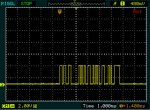
DE = DRIVER ENABLE, pull high to enable data transmit
RE = RECIEVE ENABLE, pull low to enable data recieve.

These pins are commonly tied together so that a single signal control circuit can enable either mode by placing a high or low on the line. You could permanently wire DE to high and RE to low so no control signal is needed. However all data sent would be received as if the device is listening to itself alongside any data received from the other device.
 

therooster2001

Active member
824
43
28
Location
Colorado
Well, I tested, and I think I have the wrong code. I think the instructional is dead wrong. I am only trying to receive, so I really don't need to transmit EVER.
Here is the code. I think this code (which is entitled The SAE J1708/J1587 Monitoring Sketch) is backwards. I believe that using this code, it is LOW, so set to receive, then goes HIGH, and checks for data, which they say it needs to do. I don't believe it, and as I understand it, it needs a LOW. period.
Code:
[COLOR=#323333][FONT=Courier][SIZE=2][COLOR=#008000]#define RSE 14[/COLOR][/SIZE][/FONT][/COLOR]
[COLOR=#323333][FONT=Courier][SIZE=2][COLOR=#008000]void setup() **
   Serial.begin(115200);
   Serial1.begin(9600);[/COLOR][/SIZE][/FONT][/COLOR]
[COLOR=#323333][FONT=Courier][SIZE=2][COLOR=#008000]   digitalWrite(RSE, LOW);
   delay(100);
}[/COLOR][/SIZE][/FONT][/COLOR]
[COLOR=#323333][FONT=Courier][SIZE=2][COLOR=#008000]void loop() **[/COLOR][/SIZE][/FONT][/COLOR]
[COLOR=#323333][FONT=Courier][SIZE=2][COLOR=#008000]    // Declarations
   unsigned char sBuffer[100];
   digitalWrite(RSE, HIGH);[/COLOR][/SIZE][/FONT][/COLOR]
[COLOR=#323333][FONT=Courier][SIZE=2][COLOR=#008000]    // Check for RS485 data[/COLOR][/SIZE][/FONT][/COLOR]
[COLOR=#323333][FONT=Courier][SIZE=2][COLOR=#008000]   int nBytes = Serial1.available();
   if(nBytes > 0)
   **
       int nCount = Serial1.readBytes(sBuffer, nBytes);
       for(int nIndex = 0; nIndex < nCount; nIndex++)
       **
           Serial.print(sBuffer[nIndex], HEX);
           Serial.print(" ");
       }// end for
   } //end if
}// end loop[/COLOR][/SIZE][/FONT][/COLOR]

I believe, I am just going to get away with a simple receive, something like this, and not even hook up the TX1 connection to DI, as it's never needed (or wanted), I'll just connect up RO.

Code:
[COLOR=#008000][FONT=Arial][FONT=monospace]#define RSE 14[/FONT][/FONT]
[FONT=monospace]void setup() **
   [/FONT][FONT=monospace]Serial.begin(115200);
   Serial1.begin(9600);
   digitalWrite(RSE, LOW);
   // delay(100); commented this one out, as I don't want to miss anything.  
}[/FONT]
[FONT=Arial][FONT=monospace]void loop() **[/FONT][/FONT]
[FONT=Arial][FONT=monospace]    // Declarations
   unsigned char sBuffer[100];
[/FONT][/FONT]
[FONT=Arial][FONT=monospace]    // Check for RS485 data
   int nBytes = Serial1.available();
   if(nBytes > 0)
   **
       int nCount = Serial1.readBytes(sBuffer, nBytes);
       for(int nIndex = 0; nIndex < nCount; nIndex++)
       **
           Serial.print(sBuffer[nIndex], HEX);
           Serial.print(" ");
       }// end for
   } //end if
}// end loop[/FONT][/FONT][/COLOR]


The HUlk

Member
469
7
18
Location
Cincy, OH
I would get a scope on the data lines to see if anything is happening electrically before investing further effort. If square waves are in fact there then you'll know there is data to be read. I'm not familar with whatever programming language the code you posted is written in, however I've been coding since '82 and feel confident with making some assumptions...

It would appear in the declarations that two serial ports are referenced: "serial"'& "serial1". The baud rate for "serial1" appears to be set to 9600 which is correct for J1708. I don't see any configuration for # of data bits, # of stop bits, and parity. If these port settings do not match the J1708 standard values it would cause no recieve or garbage in. It also appears the code sets a baud rate of 115200 for "serial". Does this board have two serial ports? If so is it clear which is "serial"' & "serial1"?

For J1708 the port settings are:

baud = 9600
data bits = 8
stop bits = 1
parity = none

This is a commonly used serial configuration in which many device ports are set to by default, however I would set these values in my declarations to rule out any mismatch.
 

tobyS

Well-known member
4,820
815
113
Location
IN
Reminds me of the famous saying; "What we have is a failure to communicate" (Cool Hand Luke).
 

therooster2001

Active member
824
43
28
Location
Colorado
Hulk, yes the Arduino has 2 serials. Serial is the USB, and Serial1 is the TX and RX on the board. So when we enable serial, I can see the output across a terminal like screen right from the USB that is powering the Arduino. The default for both serials is 8N1, so all good there. Its on an Arduino Leonardo for those dying to know. And I neglected to say I multi metered the pins and did receive two different results depending on Eaton and Dana, which is a bit misleading, because I can't see the waves. I did not have time to lug the new scope up there as I had only 30 min to get there and get out (getting stuff for the wife out of the garage), so that is still the intention, because I am shooting a bit in the dark, but I am confident that both models are providing something electrical out of the J1708 pins. I am just a little frustrated that when trying to learn the protocol and moreover the Max485, I ran into conflicting tutorials. It happens, but it's not like a semicolon was in the wrong place, I really do think the state is reversed. I will probably be able to test both this weekend (scope and reduced code above), so hopefully we will have an answer.

This will be the first time scoping as well, which will be extra awkward with that behemoth in the truck with me. "bench testing" a 5-ton.....
 

The HUlk

Member
469
7
18
Location
Cincy, OH
Perhaps putting 24V on a pulled module and bench testing it in the comfort of your home would be easier than on a 5-ton until you establish communications?
 

therooster2001

Active member
824
43
28
Location
Colorado
Perhaps putting 24V on a pulled module and bench testing it in the comfort of your home would be easier than on a 5-ton until you establish communications?
Yeah, I was considering that lately, it would at least give me a bunch of error codes I could immediately deal with. I have the pin outs, so not a bad idea. I was hoping this would be easier and quicker, and with no idea the signal, I should have started with a scope. I really thought I would just pick the signal up quickly, but I keep running into issues with a seemingly simple problem. I am just reading a known signal from a wire. I am using this as another learning experience, but it is definitely a back burner project, so it looks like I've been floundering for a year, but in actuality, It's just tough to keep running back and forth to the truck (about 20 miles away) to test, then realize it's a stupid mistake (like the the jumpers, or the wrong direction of states). I am a newbie at scopes so it's a bit of hesitation so I don't do the wrong thing, read it wrong or something silly. Sometimes when you tackle new things, you need to learn more about more things. J1708 protocols, RS485 IC's, and now scopes. All new to me. Armed with a good diagram, but no knowledge of IF the actual ECU is outputting the signal,and no one to confirm flashes or even to talk to about the ECU is a little like stumbling in the dark,and is literally reverse engineering 30 year old technology. I am convinced I will get it, and we will have some sort of Nirvana with what codes it's outputting. I bet it will still be "you have an air leak somewhere" 75% of the time. I do best with a buddy to bounce those ideas off of, so thanks all for the ideas and encouragement.
 

The HUlk

Member
469
7
18
Location
Cincy, OH
Yeah, take a module home, power it up and work there. Progress will improve greatly I believe.

Don't let the scope intimidate you with all of the switches & knobs, they're really quite simple to use. It's just a voltmeter that shows you what the voltage is over a period of time rather than a single moment. The vertical axis is the voltage level, and the horizontal axis is time. It's like a chart recorder if that makes sense. There are two main settings to deal with. The vertical setting or volt/div knob is scaling for voltage. If you're measuring something where the voltage changes a very small amount than this knob would be set at one end of the range or a large change in voltage would be at the other end of the range. Like adjusting the sensitivity of the chart recorder. Same situation with the horizontal setting or time/div knob. Changes that happen very quickly would be set at one end of the range and slower changes at the other end of the range. Like adjusting the speed of the chart recorder. You just adjust these knobs to zero in on the detail you are looking for which should look like the image below. I'm sure there are probably some good YouTube videos if you search "how to use an oscilloscope". Much easier to see it in action than to read about it.
 

Attachments

Last edited:

therooster2001

Active member
824
43
28
Location
Colorado
Yeah, good old YouTube, I've poured through a bunch of them and have the actual manual, so have read and digested them all, and played with the scope a couple of times as well. My triggers are the only confusing part so far (too many options there), but does have Auto. I left my harness up by the truck, but have plenty of ECU's to power up at home. About to go on work travel again, so unfortunately have more time to think and write than I do actually to test..
 
Last edited:

therooster2001

Active member
824
43
28
Location
Colorado
Well, bench test.

IMG_9258.jpg

And a waveform.

IMG_9259.jpg

I got to test it for only a bit and had to put it down for dinner. More tomorrow.


Sent from my iPhone using Tapatalk
 
Last edited:

therooster2001

Active member
824
43
28
Location
Colorado
I can't get that waveform back, and that doesn't look like data to me. I am testing on an old Eaton, as that's all I have back at the house. I'll try to grab the DANA today / tomorrow, before I go on work travel.

For what its worth, I get with a multimeter

100mV out of pin N - J1708B
1mv out of pin a - J1708A
 

The HUlk

Member
469
7
18
Location
Cincy, OH
Congratulations on your newly acquired skill of using a scope. Yeah that waveform looks like it has some flat edges but not what data should look like. Have you tried probing the scopes test point to see if you get a nice square wave? Also, where did you connect the probe & ground to take readings? You may try probing a data line on the Arduino to confirm the scope/probe is sound.
 
Last edited:

therooster2001

Active member
824
43
28
Location
Colorado
Probe is 100% on the test point. Nice and square waves, all trimmed up with the probe adjust. I think there isn't anything on the Eaton's. Headed to go grab the DANA from the garage (and try the Arduino code with just a pulled LOW). It's 70 degrees out here in Colorado. Need the make the most of it. There is an offhand chance that the ECU doesn't start outputting until it activates at the 85PSI or so. I doubt it, that would be lame diagnostics, but I've seen worse. Fingers crossed on the DANA. It will come back with me. Its actually referenced in the DANA manuals.
 

therooster2001

Active member
824
43
28
Location
Colorado
Well, the DANA does nothing out of the J1708, but has a nice waveform out of the J1939 ports. I have a CAN shield, but doesn't seem to be reading it. Sigh.

J1939 is 2.45V on the multimeter

I found the following on a J1939 site:

Summary:
In the dominant state:A typical CAN_H is about 3.5V, and a typical CAN_L is about 1.5V.
In the recessive state: the CAN_H and CAN_L are both at the same voltage level and should be about 2.5V.

SO, it looks like we have CAN info in a recessive state (whatever that is)

IMG_9262.jpg

This is both channels on the screen.
 
Last edited:
Top
AdBlock Detected

We get it, advertisements are annoying!

Sure, ad-blocking software does a great job at blocking ads, but it also blocks useful features of our website like our supporting vendors. Their ads help keep Steel Soldiers going. Please consider disabling your ad blockers for the site. Thanks!

I've Disabled AdBlock
No Thanks