• Steel Soldiers now has a few new forums, read more about it at: New Munitions Forums!

  • Microsoft MSN, Live, Hotmail, Outlook email users may not be receiving emails. We are working to resolve this issue. Please add support@steelsoldiers.com to your trusted contacts.


MEP-002A Left Connected when Main Power was Restored

Guyfang

Moderator
Staff member
Moderator
15,855
22,042
113
Location
Burgkunstadt, Germany
The L0-3 lugs are easy to find and that’s what I’ve been measuring voltage on up to this point, but I thought @Guyfang was wanting me to check were the terminals on the switch itself? (Close. What I want you to check is the input of CB1. Just like your edit down below! I just saw that. Yes, we need to make sure the CB1 is not the problem.) I found the X14,15,16 and 17 terminals on the Selector switch device inside the cabinet. I’m going to check those now.

Edit: I'm guess that by checking those wires/lugs on the S6 terminals, you eliminate the possibility of the circuit breaker being a problem?
 

Guyfang

Moderator
Staff member
Moderator
15,855
22,042
113
Location
Burgkunstadt, Germany
It looks like you are not getting excitation. There is a small canon plug that goes to the main gen. The plug is P12. Unhook P12. Test in the direction of the main gen. Continuity. That is the F1 and F2. Its a coil. Should have continuity.
 
It looks like you are not getting excitation. There is a small canon plug that goes to the main gen. The plug is P12. Unhook P12. Test in the direction of the main gen. Continuity. That is the F1 and F2. Its a coil. Should have continuity.
Ok the only small cannon plus has only two wires going into it, but goes straight to the gen. Neither the wires nor the plug nor box are labeled, but I think I can match the position of the incoming wires. Doing this with the generator off I get continuity across the two suspected pins and a resistance of 33.8 Ohms.

Edit:Just to be clear I checked the two pins in the last picture.
 

Attachments

Last edited:

Guyfang

Moderator
Staff member
Moderator
15,855
22,042
113
Location
Burgkunstadt, Germany
Roger. That looks good. Now you want to hook up the cable. Then find TB3-5 and TB3-6. You want to mesure between those two terminals, on start up. You need to see 24 volts DC there.
 
Roger. That looks good. Now you want to hook up the cable. Then find TB3-5 and TB3-6. You want to mesure between those two terminals, on start up. You need to see 24 volts DC there.
I neasured that when i check on the L0-L3 switch terminals yesterday, i'm not getting 24v there, only 115mv.
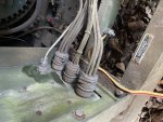
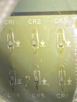
Running genset gives these measurements inside the AC control box:

L0-X14A4 = 70V
L0-X15A4 = 8.3V
L0-X16A4 = 72V

Across Terminals 3 and 5 on the TB3 gives 115mv DC
Does that mean i have 24v tansformer bad somewhere? Or some other source that is supposed to be sending 24 through that circuit?
 

Guyfang

Moderator
Staff member
Moderator
15,855
22,042
113
Location
Burgkunstadt, Germany
Need to go to your S1 switch. Pin number 27. Measure from ground to pin 27, on startup. Do you get 24 VDC? If not the S1 is bad. If you get 24 VDC, the the A4 card in the AC output box needs to be checked. The S1 sends 24 VDC to the A4, the A4 sends voltage to the F1 and F2 to light off the main gen.
 
Need to go to your S1 switch. Pin number 27. Measure from ground to pin 27, on startup. Do you get 24 VDC? If not the S1 is bad. If you get 24 VDC, the the A4 card in the AC output box needs to be checked. The S1 sends 24 VDC to the A4, the A4 sends voltage to the F1 and F2 to light off the main gen.
Ok, just so i'm clear, the S1 switch is the switch i use to prime, preheat and run the engine correct?
 
You are so fast! beat me to my edit. I found S1(yes it was the starter switch) and during cranking it was sending 22-24V. I then poked around until I found A4 (the small circuit board inside the AC output cabinet with CR1-6, a large resistor and a terminal block. I took a picture of the CR components as I think those are the diodes. These look bloated and toasted and the board appears to be slightly wavy around the components.

here is a picture of the A4 board diodes I think
 

Attachments

Last edited:

jamawieb

Well-known member
1,412
512
113
Location
Ripley/TN
You are so fast! beat me to my edit. I found S1(yes it was the starter switch) and during cranking it was sending 22-24V. I then poked around until I found A4 (the small circuit board inside the AC output cabinet with CR1-6, a large resistor and a terminal block. I took a picture of the CR components as I think those are the diodes. These look bloated and toasted and the board appears to be slightly wavy around the components.

here is a picture of the A4 board diodes I think
Diodes look good, that is the way they are suppose to look. But still test them and the 56 ohm resistor on the bottom
 

Guyfang

Moderator
Staff member
Moderator
15,855
22,042
113
Location
Burgkunstadt, Germany
To properly test a diode, at least one side/wire of the diode/circuit has to be separated from the circuit. Both sides is what I always tried to do. But at least one side. Read the directions on your tester. If something is not clear, give a shout. Oh, and dont forget to look at the back side of the card.
 
Top
AdBlock Detected

We get it, advertisements are annoying!

Sure, ad-blocking software does a great job at blocking ads, but it also blocks useful features of our website like our supporting vendors. Their ads help keep Steel Soldiers going. Please consider disabling your ad blockers for the site. Thanks!

I've Disabled AdBlock
No Thanks