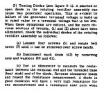
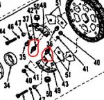
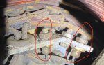
I think my PDF pages numbers are slightly different, but on my page 149, Section II, 8-2, 3a, b, c and notes state the attached. I pulled the cover off and started looking for the diodes and took pictures of the diodes on the unit, and then i came back in and referred back to the manual to get an idea of exactly what i should be looking for. When i was looking at the generator i was thinking that i was seeing at least 3 and possibly 4 diodes on each side of the exciter for a total of 6-8, but it appears that in the manual there are only 2? These are what i *think are the diodes indicated by arrows in the pictures from the genset. How many diodes are there supposed to be?
(An easy way to find out how many ANYTHING is in a set, is by looking at the -24P. For instance, the diodes. Look them up in the -24P, and you find only two diodes in the drawing with an item number. What you are looking at is one of each type diode. No need to list them all. When you look at the item description, almost all the way to the right, is a field for how many are in that figure you are looking at, (in this case 3) and the next field over shows how many total in the entire gen set, (in this case 3). That's one way. So, that means there are 3 of each kind. Total of 6. Do not mix them up. I am the kind of guy that would simply buy 6 new diodes and put them in. After all the work of getting at them, I figure its cheap insurance. Use a GOOD soldering iron. Good paste. Do not over heat them. If you just want to test, and this is the best way, un-solder them. Remove them from the heat sink. Test them, (or simply replace them) and then re-solder them to the wire.
So far the easiest way to do this seems to be to reach under the upper cabinet towards the end of the genset. What do i do for the diodes that are hidden behind the end casting of the genset that I can't reach? Would turning S1 to bump the starter until i could reach and test each one, marking the ones i tested as good and bad (if any) or is there a better method of reaching each one? (This is a way, yes. I have a small scar in my arm, from doing something very much like this. Someone who went straight to the top of my NO Christmas card list, turned on the start switch. So if you do it this way, I would unhook the main neg. battery terminal before sticking my fingers in there. Or work alone. Trust is a wonderful thing. Rare, but wonderful.
I would remove the Neg battery terminal, the remove the safety cover that allows you to remove the bolts that couple the main gen to the engine. After removing the cover, I use a pry bar to carefully move the cooling fins, and turn the main gen.
My preferred method is to simply remove the main gen end cover. Your picture shows me a main gen that has seen many years of service. Some cleaning would not hurt.


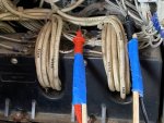 135.2 KB Views: 19
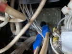 102 KB Views: 19
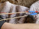 161.2 KB Views: 19

 , but I don’t think just wiping things down will do either. Thanks again.