• Steel Soldiers now has a few new forums, read more about it at: New Munitions Forums!

  • Microsoft MSN, Live, Hotmail, Outlook email users may not be receiving emails. We are working to resolve this issue. Please add support@steelsoldiers.com to your trusted contacts.


Mep 002a voltage

RJM27

Active member
Steel Soldiers Supporter
359
26
28
Location
Burdett NY
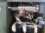
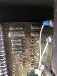
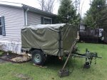
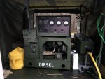
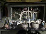
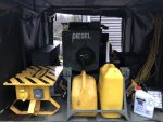
The 002a I’ve had for years, recently produces high voltage 150-300+- after start up. This happened on last 2 uses! Trailer mounted unit with 880 hrs! If I let it run for 5 mins shut down restart will go back to correct voltage. Any trouble shooting techniques would be helpful! This is a well kept & dependable unit. As always thanks for being here!!
Bob
 

Attachments

Triple Jim

Well-known member
1,373
277
83
Location
North Carolina
Bob, for some reason the output is not being regulated. From your description it seems like the full output of CVT1's X windings is being rectified by diode board A4 and being sent to the exciter field. This could happen if CVT1's control winding has a problem, or if the regulator is unable to supply regulation current to those windings. Obviously the wiring between these components will cause the problem if one gets broken or develops a high resistance connection. Since this problem is intermittent, it will be more difficult to diagnose than if it were a full time problem, but if you can catch the generator when it goes into overvoltage, shut it off and measure the control winding resistance of CVT1, you may be able to determine if it's causing the trouble.

The terminals of the control winding are C1 and C2. The resistances of those windings are in the manual TM5-6115-585-34.pdf on page 6-15. (page 93 in my PDF reader) They're specified as 9.6 ohms plus or minus 0.96 ohms.

You mentioned that you have a spare 002A, so you could also swap regulators to see if that corrects the problem.
 

RJM27

Active member
Steel Soldiers Supporter
359
26
28
Location
Burdett NY
I’ll give it a try my xtra 02 has been put into service so won’t be able to swap regulators, bummer, I had given that a thought as well!!
Thanks for the responsBob
 

Triple Jim

Well-known member
1,373
277
83
Location
North Carolina
You might also verify that T1 and T2 in the control box are working. One supplies the regulation current to the regulator board, and the other supplies a sample of the generator output to the regulator. If either one fails, the generator output will go high. Here are the voltages on the regulator board terminals of my MEP -003A.

Term Volts Function

8 7.15 DC Panel V adj. pot output
10 13 AC T2 terminal X2, gen. sample voltage to reg.
11 13 AC T2 terminal X1, gen. sample voltage to reg.
12 Ground
13 8.97 DC DC to panel adj. pot
14 16.75 DC Rectified T1 output, control current supply
15 18 AC T1 terminal X1, control current supply
16 18 AC T1 terminal X3, control current supply
17 15.18 DC Regulator Q3 collector, control current sink
18 11.13 DC Exciter field voltage
 
Last edited:

Ray70

Well-known member
2,379
5,100
113
Location
West greenwich/RI
It really would be good if you could somehow swap the regulator somehow. I've seen a couple machines where the transistors on the regulator were the cause of both intermittent and constant high voltage. I just replaced all 3 transistors and it was good to go.
Is there any way you could swap just for a while to do some testing?
Try testing the items Jim mentioned and if nothing is discovered, see if you can somehow swap out the regulator for a test.
 

RJM27

Active member
Steel Soldiers Supporter
359
26
28
Location
Burdett NY
It really would be good if you could somehow swap the regulator somehow. I've seen a couple machines where the transistors on the regulator were the cause of both intermittent and constant high voltage. I just replaced all 3 transistors and it was good to go.
Is there any way you could swap just for a while to do some testing?
Try testing the items Jim mentioned and if nothing is discovered, see if you can somehow swap out the regulator for a test.
Just what I was thinking! Lack the experience to under go the testing! Hopefully our weather will cooperate soon so I can give it a go!! I really appreciate the insight from all!
Bob
 

Guyfang

Moderator
Staff member
Moderator
15,900
22,176
113
Location
Burgkunstadt, Germany
Thanks Ray!
Everything is in the Green here. I spend 1/2 hour today holding my newest Little Warrior on my chest and whispering to him. He slept like a rock!
 

RJM27

Active member
Steel Soldiers Supporter
359
26
28
Location
Burdett NY
You might also verify that T1 and T2 in the control box are working. One supplies the regulation current to the regulator board, and the other supplies a sample of the generator output to the regulator. If either one fails, the generator output will go high. Here are the voltages on the regulator board terminals of my MEP -003A.

Term Volts Function

8 7.15 DC Panel V adj. pot output 9.4
10 13 AC T2 terminal X2, gen. sample voltage to reg. 18.3
11 13 AC T2 terminal X1, gen. sample voltage to reg. 18.3
12 Ground good
13 8.97 DC DC to panel adj. pot 12.2
14 16.75 DC Rectified T1 output, control current supply 22.5
15 18 AC T1 terminal X1, control current supply 25.5
16 18 AC T1 terminal X3, control current supply 25.5
17 15.18 DC Regulator Q3 collector, control current sink 21.6
18 11.13 DC Exciter field voltage 25.4
Ok today I fired her up an was not able to get it back down to normal voltage, I ran the diagnostic check on terminal board, as you can see they are all running high! I put the numbers at end of each line. I’m not sure what I’m checking for or where for T 1 T 2
This unit is just old but in great shape only 824 hrs. Any help greatly appreciated, remember you’re trying to help a 68 yr old rookie! As my Dad always said I know enough to get in trouble!!
Thanks everyone
 

Triple Jim

Well-known member
1,373
277
83
Location
North Carolina
You already checked T1 and T2, but they're located in the main control cabinet. Terminals 10 and 11 are the output of T2, and terminals 15 and 16 are the output of T1.

It looks like it's down to either the regulator or CVT1. Did you check the resistance between C1 and C2 of CVT1 to see if it's in spec?
 

RJM27

Active member
Steel Soldiers Supporter
359
26
28
Location
Burdett NY
You already checked T1 and T2, but they're located in the main control cabinet. Terminals 10 and 11 are the output of T2, and terminals 15 and 16 are the output of T1.

It looks like it's down to either the regulator or CVT1. Did you check the resistance between C1 and C2 of CVT1 to see if it's in spec?
Thanks, I’ll do my best to locate CVT1 c1 c2, weather change, may take day or two. Appreciate the help
 
Top
AdBlock Detected

We get it, advertisements are annoying!

Sure, ad-blocking software does a great job at blocking ads, but it also blocks useful features of our website like our supporting vendors. Their ads help keep Steel Soldiers going. Please consider disabling your ad blockers for the site. Thanks!

I've Disabled AdBlock
No Thanks